International Research Journal of Engineering and Technology (IRJET) e-ISSN: 2395-0056

Volume: 09 Issue: 11 | Nov 2022 www.irjet.net p-ISSN: 2395-0072

International Research Journal of Engineering and Technology (IRJET) e-ISSN: 2395-0056
Volume: 09 Issue: 11 | Nov 2022 www.irjet.net p-ISSN: 2395-0072
Dept. of Electrical and Electronics Engineering, JNTU College of Engineering, Hyderabad, India
Inthis paper,a gridconnected photovoltaicsystem with Fuzzy MPPT tracking and avoltage balancing converter forNPCmultilevelinvertersispresented.Byutilizingthe appropriate switching states, all switched capacitors employed in this converter will be capable of effectively equalize the DC link capacitor's voltage. Without using the magneticcomponents,suchbalancingconverter will becapableofraisingtheDC inputvoltagetothedesired voltage level. This feature enables the converter to function while guaranteeing self-balancing while providing the ability to raise the input voltage to the appropriateoutputvalue.
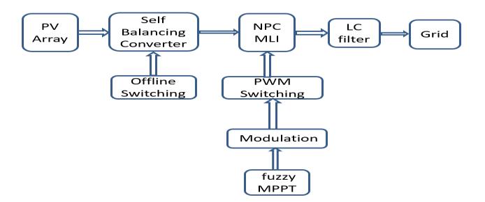
The designed converter can be employed in a gridconnectedsolarphotovoltaicsystemwithaNeutralPoint ClampedMultilevel inverter that is managed by a vector controlmethod.Totrackthemaximumpowerpointofa Photovoltaic panel, fuzzy MPPT has been employed. Under fluctuating solar irradiances, an NPC MLI can extract the maximum power from a Photovoltaic panel and inject power to the grid withexcellent dynamic and steady state performance. And the use of fuzzy MPPT makes the overall conversion very effective and produces least oscillations. MATLAB/ SimPowerSystem has been used to implement the developed gridconnectedsolarphotovoltaicsystemwithaccompanying controllersandMPPT.
Now-a-days the use renewable energy sources are increasing,therearedifferenttypesofrenewableenergy sources are available. To integrate these different sources with the power grid, a stable method of interconnection is required. This interconnection is effectivelyobtainedbyusingmultilevelinverters,dueto a number of benefits, including reduced harmonic distortions,lowerstanding voltageon transistors, better outputsignalquality,andtinyfiltersize.
There are principally three types of Multilevel inverters areavailable,theyareCascadedH-BridgeNeutral-PointClampedandFlyingCapacitors.Thereare variousissues with these MLIs, including: 1) CHB converters need numerous independent Dc voltage sources for their inputs[4],2)FCMLIsstrugglewithbalancingandhaving
too many capacitors in higher levels of output voltage [5], and 3) Neutral point clampedMLIs also need multiple DC sources and struggle with balance issues becauseoftheircapacitorusage.
The issue of capacitor voltage equalization of NPC-MLIs has been solved using a number of ways, according to the available literature survey [14]. When redundant states are employed for voltage balancing and preservingoutput voltage within the desired range, the switching approach used in [15] to equalize the voltage of the capacitors. However, at higher voltages the inductor size is increased by the extra circuit necessary to equalize the capacitors' voltage, creating implementation difficulties. In parallel 3-phase and 1phase NPC Multilevel inverters, voltage balancing methodforDClinkcapacitorswasprovidedin[16].
By connecting NPC Multilevel inverters in parallel, this technique allows for voltage balancing. The system in concern employs at least one converter that produces opposite voltage, which restricts the terminal voltage range and boosts the density of transistors at higher voltages. Zero sequence voltage injection is a suggested carrier based PWMtechnique in [17]. With this approach,capacitors' voltage may be balanced with the low frequency of switching and does not necessitate extramanagement.Thoughcomputationallychallenging, this approach. [18] suggests a further approach to balancing the DC link voltage. This approach utilizes theRLC circuit, which necessitates the inclusion of magneticcomponents,makingthedevicebigger. Several MPPT algorithms are proposed and some examples of these groups are as follows: There are many different types of approaches, including: 1) Perturbation and Observationmethod; 2) Incremental Conductancemethods3) Fuzzy logic and neural network-basedmethods.
The P & O method's primary flaw is that its operating point fluctuates around the Photovoltaic array's peak power point [30]. Additionally, the P & O approach nearly fails to identify the MPPTwhen the sun radiation changes quickly. The technique that relies on incremental conductance responds quickly in transient states but performs optimally in steady states with significantoscillations[31].
International Research Journal of Engineering and Technology (IRJET) e-ISSN: 2395-0056
Volume: 09 Issue: 11 | Nov 2022 www.irjet.net p-ISSN: 2395-0072
Inthispaper:
NPCmultilevel inverter topology solar photovoltaicsystemwithfuzzyMaximumpower point tracking being suggested, along with a step-up switching capacitor voltage balancing converter.Byutilizingtheappropriateswitching states, this suggested converter is capable of successfully equalize the DC link capacitor's voltage.
The implementation of Maximum power point trackingutilisingafuzzylogiccontrolleraimsto maximise the power from solar panels and minimisedisturbanceswithinoutputsignal.
Without employing any magnetic components, the proposed design may increase its dc Input voltage to the necessary level of output voltage. This system uses lesser input voltage sources because it just needs one Dc supply or Photovoltaicarray outputto providemulti-level output.
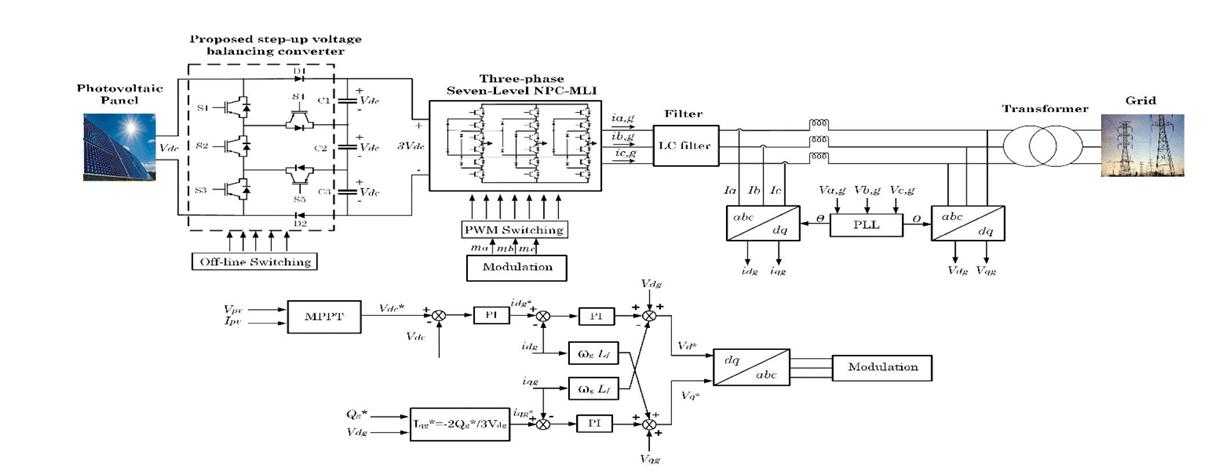
The proposed grid-connected solar Photovoltaic System with avoltage balancing converter is shown in Fig. 1. It consists of a PV array, a proposed step up converter for stabilisingthevoltageofthecapacitors,a3-phasesevenlevel Neutral Point ClampedMLI with its controllers, an LC filter to reduce total harmonic distortion, a grid interfacetransformerandapowergrid.
The suggested step upbalancing converter is supplied the output from the Photovoltaic system. When used as theintaketothesevenlevelNeutral PointClampedMLI, the balancing converter's output voltage is three times thePVvoltageinput.Throughtheuseofavectorcontrol system, the inverter is managed. The system tracks the maximum power point using fuzzy analysis. The reference DC link voltage comes from the MPPT controller'soutput.Thed-axiscurrentissuppliedmostly by DC link voltage controller's output. Based on the necessary reactive power and d-axis grid voltage, the qaxis current is determined. Controlling the d-axis and qaxis currents, correspondingly, regulates the active/reactive power flowing into the grid.
This converter is made up of two diodes, five semiconductor switches, and five capacitors. Each capacitorcanbe chargedfroma parallel connectionto a
DC source thanks to the way the converter is built. All capacitorsmustbechargedtothesameDCinputvoltage usingtheproperswitchingstates,butallcapacitorsmust be connected in series to produce the boosted output
© 2022, IRJET | Impact Factor value: 7.529 | ISO 9001:2008 Certified Journal | Page88
International Research Journal of Engineering and Technology (IRJET) e-ISSN: 2395-0056
Volume: 09 Issue: 11 | Nov 2022 www.irjet.net p-ISSN: 2395-0072
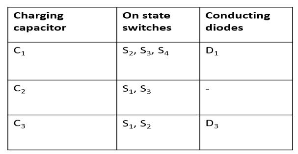
voltage. All switching states for such hypothetical converteraredisplayedinTable1.
Crisp values will become fuzzy quantities through fuzzification [34]. Fuzzy subsets are used to assign membership function values to the linguistic variable Membership function plots of the two inputs and the outputareshownindividuallyinfigure3.Thetwoinputs are fused into the Mamdani model to get required changeindutycycle.
FIG 3 Balancingconverter
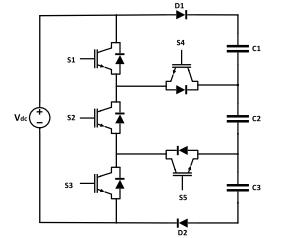
TABLE 1 Switchingstatesforbalancingconverter
Fuzzy logic control is known by its multi-rule-based resolution as well as multi-variable consideration for bothlinearandnon-linearvariationsofparameters[31]. It has the ability to work with imprecise inputs as well. Fuzzy logic system consists of 4 units specifically; Fuzzification, Rule base, Inference engine and Defuzzification[32]
In this work, we use the Mamdani approach[33]for whichtheprincipleisbasedontheselectionoftwoinput variables. In this framework, we propose the following twoinputs:
The inputs of FLC are error (E(k)) and change in error(ΔE(k)), and FLC output is varying with duty cycle(ΔD(k))which are defined by equations below. MamdanibasedFISisimplementedinthispaper.
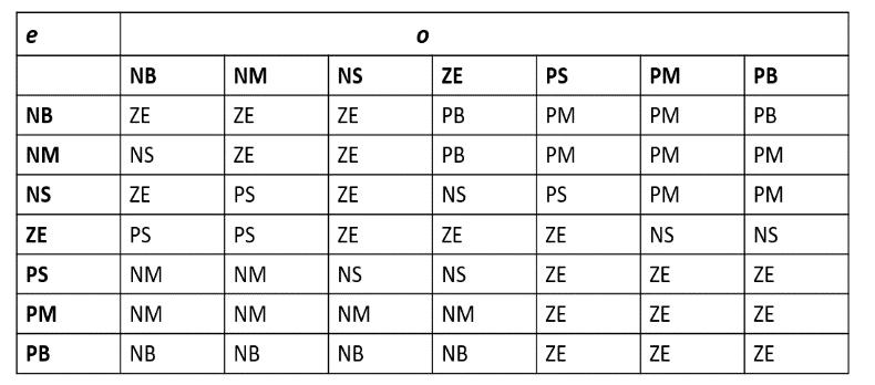
By establishing membership rules throughout this step, logical connections between the inputs and outputs are made[34]. Generally, inference engine contains fuzzy rule base and fuzzy implication sub-blocks. Rule base contains set of rules assigned to carry out different outputdependingontheinputsprovided(Table2)
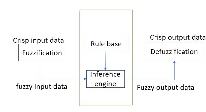
Incontrasttofuzzification,theprocessofdefuzzification involves turning fuzzy subassemblies into numerical quantities. Centre of gravity defuzzification is the technique used to assess the outcome of the suggested FLC(COG).
The Seven linguistic variables used here are: Negative Big (NB), Negative Medium (NM), Negative Small (NS), Zero Equal (ZE), positive Small (PS), Positive Medium (PM)andPositiveBig(PB) FIG
( ) ( ) ( ) (2) ( ) ( ) ( ) (3)
© 2022, IRJET | Impact Factor value: 7.529 | ISO 9001:2008 Certified Journal | Page89
International Research Journal of Engineering and Technology (IRJET) e-ISSN: 2395-0056
Volume: 09 Issue: 11 | Nov 2022 www.irjet.net p-ISSN: 2395-0072
FIG 5. Membershipfunctionsforthefuzzylogiccontroller's inputsandoutputs
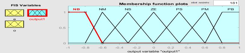
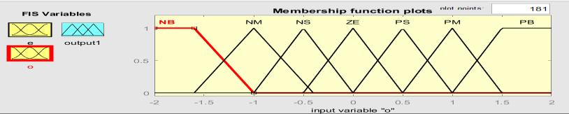
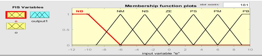
FIG 6 Graphicalrepresentationoffuzzyrules
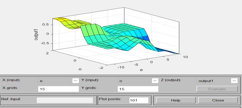
FIG 7. (a)ChargingStateofC3whenVab =0(b)ChargingStateofC3 whenVab =1Vdc (c)ChargingStateofC2whenVab =2Vdc (d)ChargingStateofC1 whenVab =+3Vdc
As can be seen, capacitors must be charged to their full potential, which is equivalent to an input DC voltage (1Vdc). By coupling the balancing network and the Neutral Point Clampedconverter, it is possible to enhanceandbalancethevoltage.
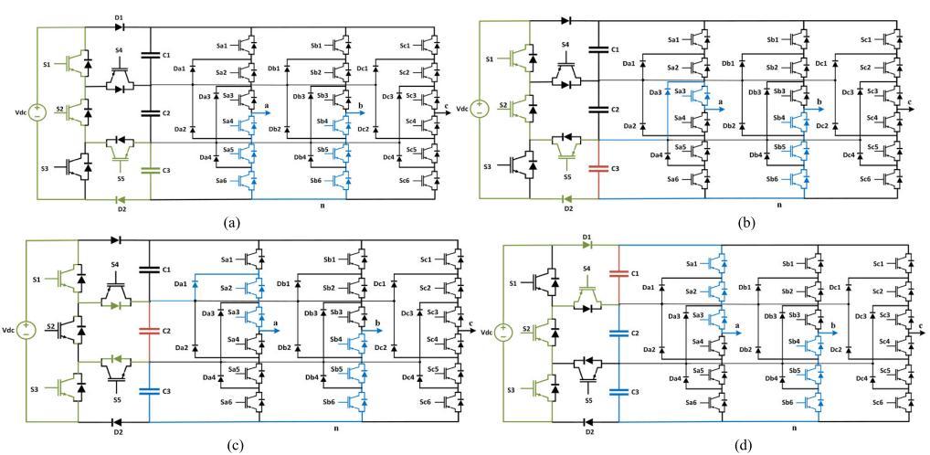
It is obvious that the green colour represents the charging path, the blue colour the discharging path, and the red colour the capacitors that are simultaneously charging and discharging. Additionally, Fig. 7 (a) shows the Vab = 0 state. It is important to note that each capacitor can be charged one additional time compared toothercapacitors.Thestateofthecapacitors'balancing determineswhichcapacitormustbechargedoncemore.
In Fig. 7(b), capacitor C3 is simultaneously charging and the voltage level between terminals “a” and “b"is +1Vdc The capacitor C2 is going to charge as indicated by the voltage level across points ab equalling Vab = +2Vdc (Fig. 7(c)). Fig. 7 also displays the capacitor C1's charging statusandtheterminalvoltagevalueof+3Vdc (d).
Fig. 1 depicts the grid side multilevel inverter's control structure. The grid linked converter employs the vector controltechnique.Thefollowingmethodscanbeusedto obtain the reactive and active power provided to the grid:
© 2022, IRJET | Impact Factor value: 7.529 | ISO 9001:2008 Certified Journal | Page90
International Research Journal of Engineering and Technology (IRJET) e-ISSN: 2395-0056
Volume: 09 Issue: 11 | Nov 2022 www.irjet.net p-ISSN: 2395-0072
(4)
where Vg, Ig, and stand for the grid's average phase voltage,averagecurrent,andaveragepowerfactorangle, respectively. The carrier-based PWM technique is applied to the inverter with in grid connected Photovoltaic, as explained in the next section. The followingarethed-andq-axisvoltages: (5) (6)
Thereactiveandactivepowercouldbestatedasfollows ifsuchvoltagevectorisparalleltothed-axis,Vqg=0,and Vdg=Vg
( ) | | (7)
( ) | | (8)
Theaforementionedequationsdemonstratethatwemay easily regulate the reactive and active power by adjustingtheq-axisandd-axiscurrents.
Toachievethevoltageoutputwith seven levelsutilising the right switching frequency, a carrier basedPWM
The incremental conductance-based algorithm providesaquickreactionintransientconditions but performs optimally with significant oscillationsinconstantconditions.
schemeisselected.Inordertogenerateswitchingpulses and a seven-level output voltage, six triangular carrier waveformsareused,togetherwithareferencevoltage.
(9)
atma =1,theRMSfundamentallinetolinevoltageis: ( ) ( ) (10)
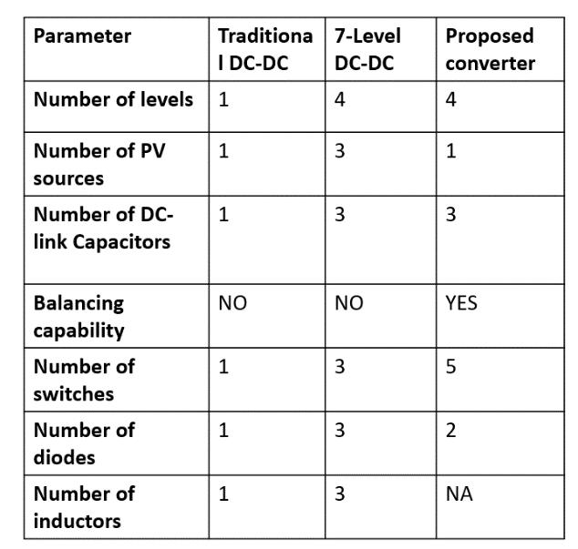
A. Comparative analysis with traditional DC-DC converters
The P&O technique of MPPT has the disadvantage that, in steady state, the voltage leveloscillatesabouttheMPP,leadingtotheloss ofsomeavailableenergy.
greater than those acquired from a traditional solarmodule.
The greatest application of fuzzy logic has been itsabilitytofunctionwithimpreciseinputswith noneedforanaccuratemathematicalmodeland abletodealwithnonlinearity.
• FLC has the benefit of being reliable and very simple to construct, and it does not necessitate perfect understanding of the regulator. There is nooscillationinthisalgorithm;itoperatesatthe best point. It is also distinguished by good conductwhileinafleetingstate.
Through a rigorous simulation analysis using MATLAB/SimPowerSystem, the proposed approach of integrating solar PV systems with the grid is thoroughly validated in this part. In this simulation, the suggested converter topology is used to study a 1.14 kw gridconnectedsolarPVsystem.
Parameter values
The Fuzzy control algorithm converges quickly andwithoutoscillation
• PVModule:BIPV054-T86
•
The output power as well as voltage derived from the fuzzy logic based MPPT system are
28.8V Voltage at MPP (VMPP),6.6A MPP Current (IMPP)
© 2022, IRJET | Impact Factor value: 7.529 | ISO 9001:2008 Certified Journal | Page91
International Research Journal of Engineering and Technology (IRJET) e-ISSN: 2395-0056
Volume: 09 Issue: 11 | Nov 2022 www.irjet.net p-ISSN: 2395-0072
• The entire PV array consists of 1 string with a Total Power of 1.14kW @ 172.8 V and a string madeupof6modules.
• SwitchingFrequency:5KHz.
• TheSamplingtime:50µs.
• OutputFrequency:50Hz.
• CapacitorValue:4700µf.
• Outputfilter:L=12mHandC=2.5µf.
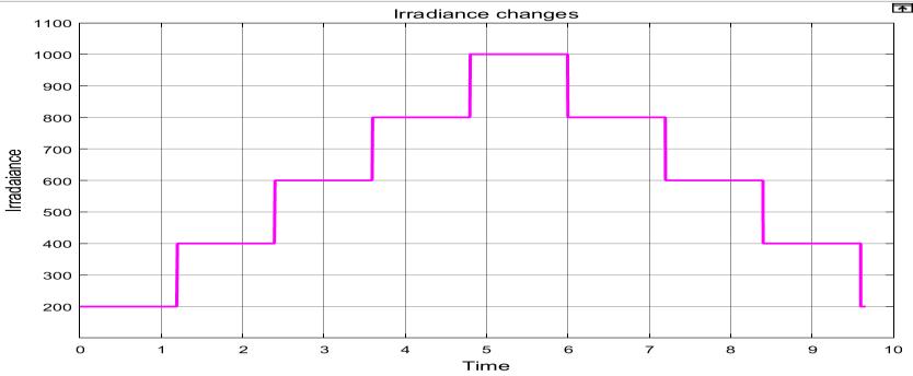
• The irradiations are varied as follows - 200 W/m2(0<t<1.2s),400W/m2(1.2s<t<2.4s),600 W/m2 (2.4s<t<3.6s) ,800 W/m2 (3.6s< t<4.8), 1000W/m2(4.8s<t<6s),800W/m2(6s<t<7.2s) ,600 W/m2 (7.2s<t< 8.4s) ,400 W/m2 (8.4s<t<9.6s),200W/m2(9.6s<t<10s)
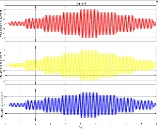
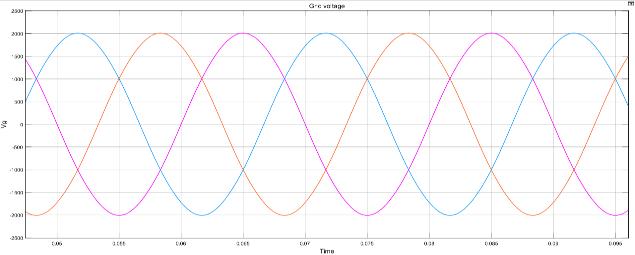
Fig.8-19displaysthesimulationstudy'sresultsinterms of responses. The balanced output of the three phase NPC-MLI in Figure 8 serves as a demonstration of the developed converter's ability to balance voltage. The diagram shows where each phase voltage has three levels in each of the positive and negative half-cycles, plusonezerolevel,foratotalofsevenlevels. Thephase currents ofa,bandc Phases oftheMLIhasbeen shown inFig.9
FIG 9 OutputCurrentofNPCMLI
In the other words, the Photovoltaic array voltage monitors the needed MPPT voltages with the changing irradianceto ensure thatthehighestpossibleamountof solarpowerisextracted,comprehensivelyvalidatingthe system.
Figs. 10, 11, and 12 show, respectively, the voltage and currentofthePVarrayaswellasthevoltagesacrossthe DC link capacitor. Fig. 10 shows that the reference and actual PV voltages change as well as the Photovoltaic voltageforMPPTatvariousirradiances.
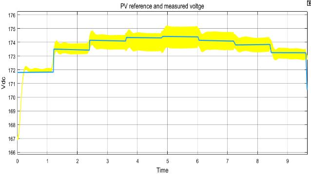
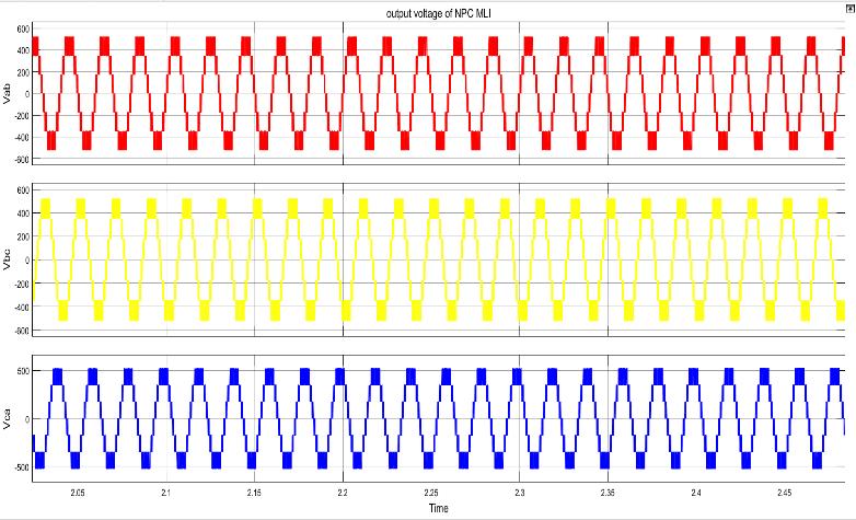
FIG 10.SimulationResultsforPVReferenceand Measuredvoltage
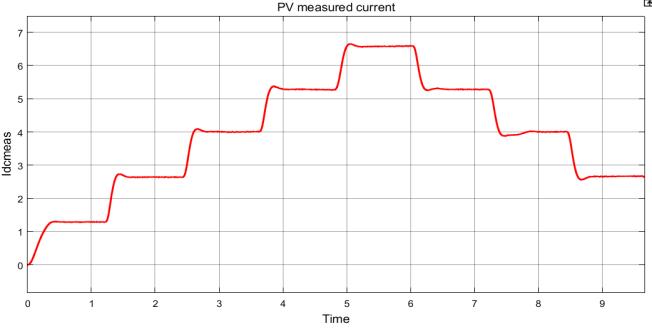
FIG 11.SimulationResultsforPV’sMeasuredCurrent
© 2022, IRJET | Impact Factor value: 7.529 | ISO 9001:2008 Certified Journal | Page92
International Research Journal of Engineering and Technology (IRJET) e-ISSN: 2395-0056
Volume: 09 Issue: 11 | Nov 2022 www.irjet.net p-ISSN: 2395-0072
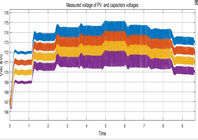
Figure13displays thecurrentsandvoltagesofswitches S1,S2,andS3 withinvoltagebalancingconverter.
FIG 15.SimulationResultsGridCurrentunderdifferent irradiances
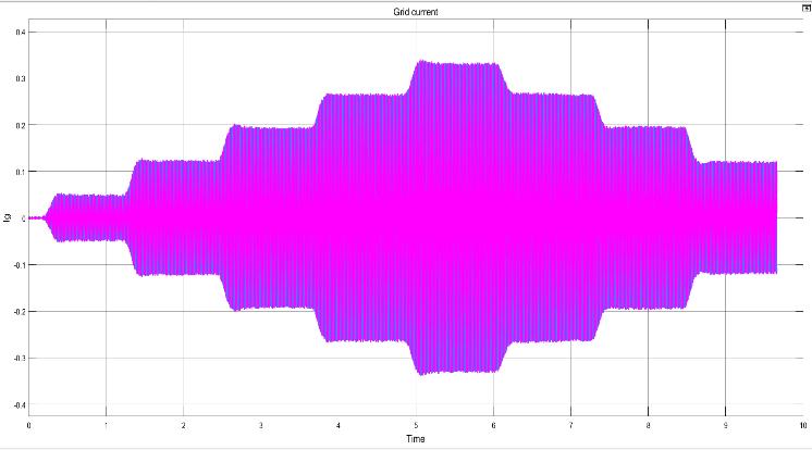
Figures14and15,whichshowthe3-phasegridcurrent and voltage, respectively, validate the voltage balancing & boosting with the better power quality in grid linked operation. The current response indicates that the ac current going to the grid varies in response to changing irradiation levels and ensures export of the maximum amount of solar power under varying weather conditions(Fig.18).
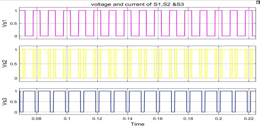
FIG 13.VoltageandcurrentofS1,S2andS3 FIG 14
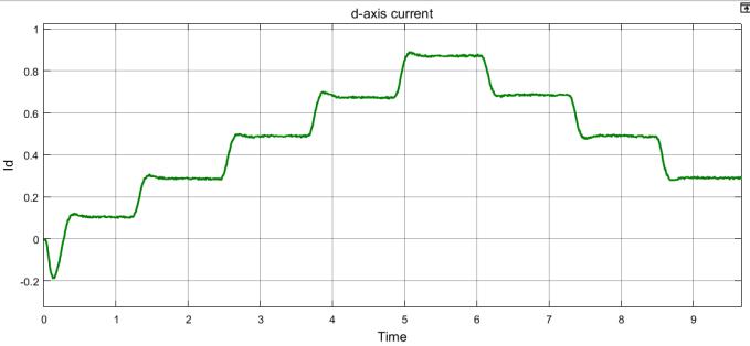
FIG 16.SimulationResultsford-axisCurrentunder differentirradiations.
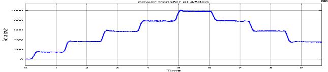
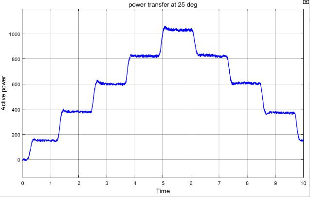
The tracking of the d-axis current is depicted in Fig. 16 and indicates that current is closely tracking the necessary reference value to guarantee the transfer of the greatest amount of solar energy to the grid. Additionally, Figs. 18 and 19 depict the power
International Research Journal of Engineering and Technology (IRJET) e-ISSN: 2395-0056
Volume: 09 Issue: 11 | Nov 2022 www.irjet.net p-ISSN: 2395-0072
transmission to a grid (Figure. 18 at 25°; Fig. 19 at 45°) in response to changes in temperature and irradiance (Fig.16).
multilevel inverter for renewable energy integration and drives application: Topologies, comprehensive analysis and comparative evaluation,’’ IEEE Access, vol. 7, pp. 54888–54909,2019.
2) S. Shuvo, E. Hossain, T. Islam, A. Aqib, S. Padmanabhan, and M. Z. R. Khan, ‘‘Design and hardware implementation considerations of modifiedmultilevel cascadedH-Bridgeinverter for photovoltaic system,’’ IEEE Access, vol. 7, pp.16504–16524,2019.
FIG 18.Powertransfertothegridattemperature25◦ c underdifferentirradiations
3) F. Z. Peng, ‘‘A generalized multilevel inverter topology with self-voltage balancing,’’ IEEE Trans. Ind. Appl., vol. 37, no. 2, pp. 611–618, Mar./Apr.2001.
4) A.Taghvaie,J.Adabi,andM.Rezanejad,‘‘Aselfbalanced step-up multilevel inverter based on switched-capacitor structure,’’ IEEE Trans. PowerElectron.,vol.33,no.1,pp.199–209,Jan. 2018.
5) V. Dargahi, A. K. Sadigh, M. Abarzadeh, S. Eskandari, and K. A. Corzine, ‘‘A new family of modular multilevel converter based on modified flying-capacitor multicell converters,’’ IEEE Trans. Power Electron., vol. 30, no. 1, pp. 138–147,Jan.2015.
FIG 19 Powertransfertothegridattemperature45◦ c underdifferentirradiations
This research has created a brand-new step-up voltage balancingconverterinphotovoltaicsolarsystemsthatis appropriateforNPC-MLI.Thecreatedconverternotonly increasestheinputPVvoltagetotheappropriateoutput level, but it also eliminates the magnetic components, lowering the system's weight and cost. Additionally, producing multi-level output only needs one Dc supply or PV array output, which lowers the quantity ofinput voltagesneededinsuchsystems.
According to the simulation results, the designed topology using fuzzy MPPT can efficiently equalize the DC-linkvoltage,collectthemostpowerpossiblefromPV modules, and inject electricity into the grid under a rangeofsolarirradianceswithexcellentsteady-stateand dynamic performances. As a result, it's been demonstrated that controllers of this type also manage stablefunctioning.
1) P. R. Bana, K. Panda, R. T. Naayagi, Siano, G. Panda, ‘‘Recently developed reduced switch
6) J.Shen,S.Schroder,R.Rosner,andS.El-Barbari, ‘‘A comprehensive study of neutral-point selfbalancing effect in neutral-point-clamped three-level inverters,’’ IEEE Trans. Power Electron., vol. 26, no. 11, pp. 3084–3095, Nov. 2011.
7) A. Nabae, I. Takahashi, and H. Akagi, ‘‘A new neutral-point-clamped PWM inverter,’’ IEEE Trans.Ind.Appl.,vol.IA-17,no.5,pp.518–523, Sep.1981.
8) A. Tripathi and G. Narayanan, ‘‘Torque ripple minimization in neutral point-clamped threelevel inverter fed induction motor drives operated at low-switching-frequency,’’ IEEE Trans. Ind. Appl., vol. 54, no. 3, pp. 2370–2380, May2018.
9) W. Zeng, R. Li, and X. Cai, ‘‘A new hybrid modular multilevel converter with integrated energy storage,’’ IEEE Access, vol. 7, pp. 172981–172993,2019.
10) M. H. Ahmed, M. Wang, M. A. S. Hassan, and I. Ullah,‘‘Powerlossmodelandefficiencyanalysis of three-phase inverter based on SiC MOSFETs
© 2022, IRJET | Impact Factor value: 7.529 | ISO 9001:2008 Certified Journal | Page94
International Research Journal of Engineering and Technology (IRJET) e-ISSN: 2395-0056
Volume: 09 Issue: 11 | Nov 2022 www.irjet.net p-ISSN: 2395-0072
for PV applications,’’ IEEE Access, vol. 7, pp. 75768–75781,2019.
11) B.R.LinandT.C.Wei,‘‘AnovelNPCinverterfor harmonics elimination and reactive power compensation,’’IEEETrans.PowerDel.,vol.19, no.3,pp.1449–1456,Jul.2004.
12) H.Akagi,H.Fujita,S.Yonetani,andY.Kondo,‘‘A 6.6-kV transformer less STATCOM based on a five-level diode-clamped PWM converter: System design and experimentation of a 200-V 10-kVA laboratory model,’’ IEEE Trans. Ind. Appl.,vol.44,no.2,pp.672–680,Mar.2008.
13) H. Xiao and S. Xie, ‘‘Transformer less splitinductor neutral point clamped three-level PV grid-connected inverter,’’ IEEE Trans. Power Electron., vol. 27, no. 4, pp. 1799–1808, Apr 2012. VOLUME 8, 2020 83951 A. Taghvaie et al.: New Step-Up Switched-Capacitor Voltage BalancingConverter
14) N.Celanovic & D. Boryevich, ‘‘A comprehensive study of neutral point voltage balancing problem in 3-level neutral-point-clamped voltage source PWM inverters,’’ IEEE Trans. PowerElectron.,vol.fifteen no.2,pp.242–249, Mar.2000.
15) A. Nami, F. Zare, A. Ghosh, & F. Blaabjerg, ‘‘A hybrid cascade converter topology with seriesconnected symmetrical & asymmetrical diodeclamped H-Bridge cells,’’ IEEE Trans. Power Electron.,vol.26,no.1,pp.51–65,Jan.2011.
16) R.Stala,‘‘AnaturalDC-linkvoltagebalancingof diode-clamped inverters in parallel systems,’’ IEEE Trans. Ind. Electron., vol. 60, no. 11, pp. 5008–5018,Nov.2013.
17) J. Pou, J. Zaragoza, S. Ceballos, M. Saeedifard, and D. Boroyevich, ‘‘A carrier-based PWM strategy with zero-sequence voltage injection for a three-level neutral-point-clamped converter,’’ IEEE Trans. Power Electron., vol. 27,no.2,pp.642–651,Feb.2012.
18) R. Stala, ‘‘Application of balancing circuit for DC-link voltages balance in a single-phase diode-clamped inverter with two three-level legs,’’ IEEE Trans. Ind. Electron., vol. 58, no. 9, pp.4185–4195,Sep.2011.
19) A. Nami, F. Zare, A. Ghosh, and F. Blaabjerg, ‘‘Multi-output DC–DC converters based on diode-clamped converters configuration:
Topology and control strategy,’’ IET Power Electron.,vol.3,no.2,pp.197–208,2010.
20) V.Yaramasu,B.Wu,M.Rivera,andJ.Rodriguez, ‘‘Anewpowerconversionsystemformegawatt PMSGwindturbinesusingfour-levelconverters andasimplecontrolschemebasedontwo-step model predictive strategy Part I: Modeling and theoretical analysis,’’ IEEE J. Emerg. Sel. Topics Power Electron., vol. 2, no. 1, pp. 3–13, Mar.2014.
21) V.Yaramasu,B.Wu,M.Rivera,andJ.Rodriguez, ‘‘Anewpowerconversionsystemformegawatt PMSGwindturbinesusingfour-levelconverters andasimplecontrolschemebasedontwo-step model predictive strategy Part II: Simulation and experimental analysis,’’ IEEE J. Emerg. Sel. Topics PowerElectron.,vol.2,no.1,pp.14–25, Mar.2014
22) Y. Chen and K. Smedley, ‘‘Three-phase boosttype grid-connected inverter,’’ IEEE Trans. Power Electron., vol. 23, no. 5, pp. 2301–2309, Sep.2008.
23) P. Kolahian, H. Tarzamni, A. Nikafrooz, and M. Hamzeh, ‘‘Multi-port DC–DC converter for bipolar medium voltage DC micro-grid applications,’’ IET Power Electron., vol. 12, no. 7,pp.1841–1849,Jun.2019.
24) A. Taghvaie, M. E. Haque, S. Saha, and M. A. Mahmud, ‘‘A new step-up voltage balancing circuit for neutral-point-clamped multilevel inverter,’’ in Proc. IEEE Int. Conf. Power Electron., Drives Energy Syst. (PEDES), Dec. 2018,pp.1–6.
25) S. Saha, M. E. Haque, C. P. Tan, and M. A. Mahmud, ‘‘Sensor fault resilient operation of permanent magnet synchronous generatorbased wind energy conversion system,’’ IEEE Trans. Ind. Appl., vol. 55, no. 4, pp. 4298–4308, Jul.2019.
26) J. I. Leon, S. Vazquez, and L. G. Franquelo, ‘‘Multilevel converters:Control andmodulation techniques for their operation and industrial applications,’’ Proc. IEEE, vol. 105, no. 11, pp. 2066–2081,Nov.2017.
27) B.Wu,‘‘CascadedHBridgemultilevelinverters,’’ in High-Power Converters and AC Drives. Hoboken,NJ,USA:Wiley,2006,pp.119–142.
© 2022, IRJET | Impact Factor value: 7.529 | ISO 9001:2008 Certified Journal | Page95
International Research Journal of Engineering and Technology (IRJET) e-ISSN: 2395-0056
Volume: 09 Issue: 11 | Nov 2022 www.irjet.net p-ISSN: 2395-0072
28) Y. C. Fong, S. R. Raman, Y. Ye, and K. W. E. Cheng, ‘‘Generalized topology of a hybrid switched-capacitormultilevelinverterforhighfrequency AC power distribution,’’ IEEE J. Emerg. Sel. Topics Power Electron., early access, Mar. 15, 2019, doi: 10.1109/JESTPE.2019.2905421.
29) P. Barbosa, P. Steimer, J. Steinke, M. Winkelnkemper, and N. Celanovic, ‘‘Activeneutral-point-clamped (ANPC) multilevel converter technology,’’ in Proc. Eur. Conf. PowerElectron.Appl.,Sep.2005,p.10.
30) H. Rezk, M. Aly, M. Al-Dhaifallah and M. Shoyama, "Design and Hardware Implementation of New Adaptive Fuzzy LogicBased MPPT Control Method for Photovoltaic Applications", IEEE Access, vol. 7, pp. 106427106438,2019.
31) S. Z. Mirbagheri, S. Mekhilef, and S. M. Mirhassani,“MPPTwithInc.Condmethodusing conventional interleaved boost converter,”Energy Procedia, vol.42,pp.24–32, 2013.
32) R. Sankar, S. Velladurai, R. Rajaraman and J. A. Thulasi, "II. PV system description: Maximum powerextractioninPVsystemusingfuzzylogic and dual MPPT control", International Conference on Energy Communication Data Analytics and Soft Computing (ICECDS), pp. 3764-3769,2017.
33) H. Rezk, M. Aly, M. Al-Dhaifallah and M. Shoyama, "Design and Hardware Implementation of New Adaptive Fuzzy LogicBased MPPT Control Method for Photovoltaic Applications", IEEE Access, vol. 7, pp. 106427106438,2019
34) Priyabrata Shaw et al., "Modelling and control of a battery connected standalone photovoltaic system", 2016 IEEE 1st International Conference on Power Electronics Intelligent ControlandEnergySystems(ICPEICES),2016.
© 2022, IRJET | Impact Factor value: 7.529 | ISO 9001:2008 Certified Journal | Page96