International Research Journal of Engineering and Technology (IRJET) e-ISSN: 2395-0056

Volume: 09 Issue: 09 | Sep 2022 www.irjet.net p-ISSN: 2395-0072
International Research Journal of Engineering and Technology (IRJET) e-ISSN: 2395-0056
Volume: 09 Issue: 09 | Sep 2022 www.irjet.net p-ISSN: 2395-0072
1 M.Tech Scholar, Dept. of Civil Engineering, Shri Rawatpura Sarkar University, Raipur
2 Assistant Professor, Dept. of Civil Engineering, Shri Rawatpura Sarkar University, Raipur
3 Assistant Professor, Dept. of Civil Engineering, Shri Rawatpura Sarkar University, Raipur
4 Assistant Professor, Dept. of Civil Engineering, RSR Rungta College of Engineering and Technology, Bhilai ***
Abstract - The high-end water tank is made of reinforced concrete A building of great importance. They are considered the main lifeline elements during and after the earthquake. Inze tank behavior Something like an inverted pendulum made of a huge mass of water at the top of lean staging. this is the most important Consideration of tank failure during an earthquake. Basically, the support system, the so-called staging, A group of columns and horizontal brackets that form a column. staging is fully responsible for lateral resistance structure. This analysis is performed by the finite element method as follows. intze tank seismic stress in zone 4 acc Geographic Survey of India. Comparison of principles different packing states of stress and deflection occur. Applying Earthquakes and wind loads The analysis is The performs for different types of water tanks. capacity. You can run the same analysis for different earthquakes zone in India. This analysis can also be performed using different storage materials instead of water. Stress increases as water level rises The tank is due to the FSI effect of liquids, which causes stress when the tank is full. Found about twice the empty tank voltage on the state. As the amount of water increases, the deflection also increases. At the level in the tank, the stress increases and deflection occurs. The water level rises very little when the wind hits it Loads, Maximum Stresses and Deflections with Different Fillings The conditions are almost the same as for wind loads.
Key Words: structural analysis, axial force, soil, seismic zone, deflection, Maximum Stresses.
Similar to round tanks, they are provided with a conical bottomatthebottom.Moreforcesandvibrationsactonthe watertank.B.Waterpressureontankwalls,windpressure, dead weight of tank, seismic forces on base tank, and sloshing behavior of liquid in tank at different fill levels. Therefore,tofullyinvestigateawatertank,itisnecessaryto investigate the effects of all forces on the tank under different filling states, either with fluid-structure interactionsorwithoutFSI. Manystudieshavebeendonein the past on the analysis of aquaria using different loading conditions and different analytical methods. For example, variousstudiesarebeingconductedsuchasstaticanalysisof
water tanks against wind load and seismic load, free vibration analysis of water tanks, and forced vibration analysisofwatertanks.Inthisstudy,ANSYSsoftwareisused to perform a static model analysis of a water tank with a capacityof1000m3.Afiniteelementanalysisofatankfor seismicloadsatdifferentfillingstates,includingtheeffects offluid-structureinteraction,isperformedinthisstudyfor thesametankwithacapacityof1000m3.Seismicityisthe suddenmovementoftheearth'scrustcausedbytherapid releaseofcrustalenergy.Earthquakesarerelativelysevere geological disastersthatdestroyhomesandbuildingsand leadtosubsequentdisasters. Soil-structuralinteractionsare a complex phenomenon involving the effects between variouscomponentssuchasthefoundationandbearingsoil, liquidandwallsoftheliquidlayeredsoilsystemoftheIntze aquaria.ThetypicaldesignoftheIntzewatertankignores the interaction between the soil, foundation, and tank structure to simplify the analysis.Ingeneral,the effect of subsidenceofsupportingsoilonthetanksuperstructure is neglected. Previous studies have shown that interaction effects are important studies for the analysis of stresses, especiallyforstructuresplacedinhighlycompressiblesoils.
Aquarium type tanks can be divided into three categories basedonthelocationofthetankwithinthebuilding. These are: Undergroundtanks
TankisonTerrain
Overheadorelevatedtanks
Theelevatedtankhasmanyadvantages.Elevatedtanksdo notrequirecontinuousoperationofthepump.Pressureis maintained by gravity, so momentary pump stoppages do notaffectwaterpressureinthewaterdistributionsystem. The strategic placement of tanks also helps balance the waterpressure inthewaterdistributionsystem.However,it canbedifficulttocontroltheexactwaterpressureinsome elevatedtanks. Thepressureofthewaterflowingoutofthe elevatedtankdependsonthedepthofthewaterinthetank. Anearlyemptytankislikelynotprovidingenoughpressure, and a completely full tank can be providing too much pressure. Optimal pressure is reached only at one depth.
International Research Journal of Engineering and Technology (IRJET) e-ISSN: 2395-0056
Volume: 09 Issue: 09 | Sep 2022 www.irjet.net p-ISSN: 2395-0072
Optimal waterdepthfor pressurizationpurposesis more specific to standpipes than to foot-mounted tanks. The lengthofthestandpipecausesconstantandhighlyuneven pressureinthedistributionsystem.Italsorequiresalarge amountof waterinthestandpipetogeneratetherequired waterpressure.
typesofelevatedwatertanksbyshapeThe typesof tanks byshapeareasfollows:-
1. RoundTank
2. Rectangulartank
3. inzetank
InzetankSimilartotheroundtank,the bottomisprovided withaconicalbottom.Supportcanbedividedintotwotypes.
1.Pillarmountedwatertanks2ndshaftwastewatertank In general,awatertankattachedtothecolumnispreferredfor easierSOCcalculations. Manymoreforcesandvibrationsact onthewatertank,suchaswaterpressureonthetankwall, windpressure,self-weightofthetank,seismicforcesonthe base tank, sloshing behavior of the liquid in the tank at differentfillinglevels.Tofullyinvestigatetheeffectsofall forces on the tank under different filling conditions, with fluid-structure interactions or without FSI, should be investigated. Manystudieshavebeendoneinthepastonthe analysis of aquaria using different loading conditions and different analytical methods.For example,various studies arebeingconducted suchasstaticanalysisofwatertanks againstwindloadandseismicload,freevibrationanalysisof watertanks,andforcedvibrationanalysisofwatertanks.
Soilstructureinteractionistheinteractionbetweenstructure and soil called soil structureinteraction. Two mechanisms areinvolvedinthesoilstructureinteraction:(1)kinematic interaction and (2) inertial interaction. A "free field" is a space sufficiently distant from a support structure that groundmovement(calledfreefieldgroundmovement)isnot impededbymovementofadjacentstructures.Ingeneral,if thedistancetraveledbythebaseislessthanthedimensions of the base, the movement of the base will not match the movement on the ground in the field. This effect is called kinematicinteraction.Ontheotherhand,structureshavea large massandgive inertial motion to the ground,causing ground displacement. This phenomenon is called inertial interaction (Wolf1985). Structural interactions with the surrounding soil are stratified, which leads to changes in dynamicwavebehavior.Dynamicanalysismustconsiderthe interaction between structure and soil. The dynamic response of a geo-structural interaction system is the objectiveofa seismicmodelofthesystemwhensubjectedto three components, the seismic parameters of position, motion, and stimuli, and seismic loads. Site seismic parameters include Young's modulus (E), density (D), soil
Poisson's ratio, and soil damping. Attenuation can also be divided into two different types: internal attenuation and radiation attenuation. Internal attenuation is caused by kinetic waves passing through layered soil and can be consideredasa sourceof energylossduetodebrisinthe soil,whereasradiationattenuationistheenergylossdueto wave emission from the structure foundation to the structure.causeloss.Andoutsideofhemisphericreason,such analgebraicdistributionofelasticmotioniscalledgeometric damping.Properseismicanalysisofsoil-structureinteraction systemresponserequiresexcitation,includingdetermination of the various components and free-field motions of the system. Calculation of structure-free earth movement and scatteringofseismicwavesbytheinteractionsystemofsoil and structure. Following the principle of superposition, excitationsresultingfromfree-fieldandinteractionanalyzes are added, and the seismic model of the system includes dynamicmodelrelationshipsoftheunderlyingenvironment. Many models are available for considering and analyzing interactions.Soil-structureinteractionsgenerallyfallintotwo categories, direct and substructural approaches, each of whichiscomplex.
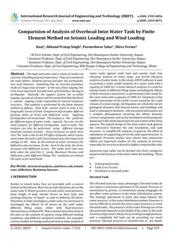
Fluid-structureinteraction(FSI)isacomplexphenomenon between laws describing fluids and structures. This phenomenon is characterized by a stable or possibly oscillating interaction between a deformable or moving structureandthesurroundingorinternalfluidflow.Whena fluidstreamimpingesonastructure,itsubjectsthefrozen part to stress and strain patterns that can cause displacement. These displacements are determined by the pressure and momentum of the flow and the material properties of theactual structureandcan beverylargeor small.Therearetwotypesofvibrationsthatoccurintank topsoftankcontainers.Theyarecalledconvectivemasses andarealwayssloshingkineticeffectsandthebottomofthe partiscalledimpactmass.
International Research Journal of Engineering and Technology (IRJET) e-ISSN: 2395-0056
Volume: 09 Issue: 09 | Sep 2022 www.irjet.net p-ISSN: 2395-0072
Finite element analysis with circular INTZE type water tank

Pretreatment:
Modeling a circular Intze Type Water Tank Model of the CurrentProblemoftheWaterline.
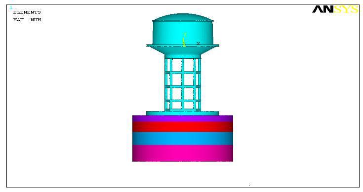
Fig -2:Mashingoftankfullhomogenousempty.
Analysis type: -
Inpresentstudywehavetoanalyzetherandomvibration analysis of water tank due to seismic loading condition. ThereforeanalysistypeusedinthisstudyisStaticandStatic andmodal
Boundary condition: -
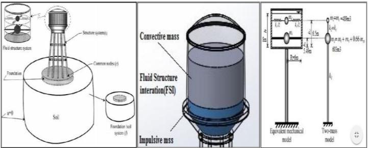
Fig -1:modelofintzwatertankbyANSYS
Item Type: Solids 187 elements are used for concrete structures.Also,theFluid30elementisusedtoindicatethe presenceofwaterinthetank. solid187elementdescription: The SOLID187elementisahighorder3Delementwith10 nodes.SOLID187hassecondorderdisplacementbehavior andissuitableformodelingirregularmeshes.Theelementis definedby10nodeswith3degreesoffreedomateachnode (displacementsinthenodaldirectionsx,y,z).Thiselement has the features of plasticity, hyperelasticity, creep, stress hardening,largedeflection,andlargeelongation.
Material model: Table 1: MaterialPropertiesUsedinAnalysis
Material used
Young’s modulus of elasticity
Poisson’s Ratio Density
Concrete 25.49Gpa 0.2 25kN/m3
Soil 1 35Gpa 0.28 17kN/m3
Soil 2 40Gpa 0.29 17.4kN/m3
Soil 3 45Gpa 0.3 18kN/m3
Soil 4 55Gpa 0.32 19.2kN/m3
Soil 5 60Gpa 0.33 19.9kN/m3 Water 10kN/m3
Mashing:
Tetrahedralfreemashingisusedforthemashingofwater tank.Andtheelementsizeistaken500mm
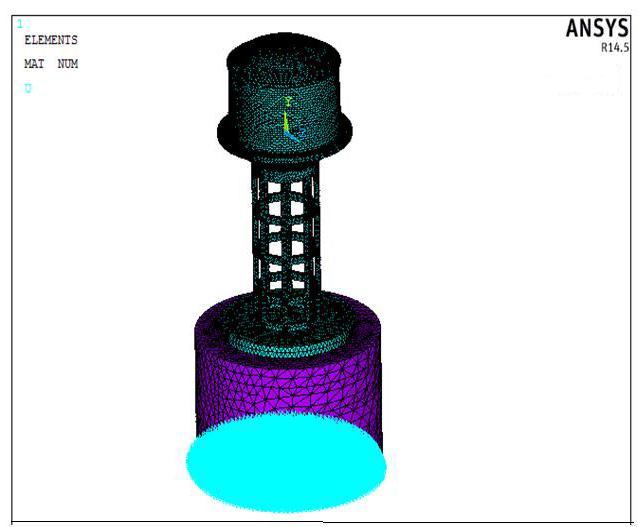
Inpresentstudytheintzetankisfixedatbase.Foranalysis offulltankonlybasearefixedbutforanalysisofsametank byhalfmodelwehavetofixthebaseaswellassymmetric boundaryconditionisalsoappliedonsymmetricportion.
Fig -3:boundaryconditionforfulltank(onlybasefixed)
InpresentstudywehavedonestaticanalysisofIntzewater tankforseismicloadingincludingfluidstructureinteraction effect due to presence of water in tank forseismic loading conditionaswell asforwindloadingcondition.Inpresent analysisweassumethatwindloadingandseismicloadingis sameinnature,bothinducedrandomeffectonanystructure but only difference is this the wind load is act on superstructure and seismic load is act on substructure of intzewatertank.
International Research Journal of Engineering and Technology (IRJET) e-ISSN: 2395-0056
Volume: 09 Issue: 09 | Sep 2022 www.irjet.net p-ISSN: 2395-0072
Thereforeinthischapterwediscusstheperformingresultsof different analysis in different loading condition on intze watertank.Theheadlinesaregivenbelow:
Static analysis of intze water tank for different loading condition including FSI effect
Staticanalysisoftankduetoseismicloading. Static analysis of tank due to only wind loading condition.
Instaticanalysiswetakeallthreecasesloadingthatcanbe appliedonanelevatedintzetypewatertank,andmutually comparetheresultsofallthreecasesandthenconcludethe worstconditionofloads.Theconditionofloadingandtheir resultsarediscussedbelow. Analysisoftankduetoseismicloading. Analysisoftankduetoonlywindloading.
Theseallstudiesandtheirresultsaregivenbelow.
Inthisanalysisweappliedanseismicloadondifferentfilling condition in the tank and plot the results for maximum principal stresses, minimum principal stresses, maximum deflection,minimumdeflection,andoverallstressesonthe inallsixfillingconditionoftank.Theresultsofthatanalysis aresummarizedingiventable.
Discussion:
maximumstressintankduetoseismicloadingisgenerated at full tank condition and the value of stress is 12.842 N/mm2andpermissiblestressofconcretewhichisusedis 25N/mm2,Stressgeneratedintankisapproximatelyhalfof thepermissiblestressoftankthereforewecanconcludethat thetankissafeinstressduetoseismicloadinginallfilling condition.Andmaximumdeflection16.3034mmoccursat topdomeintankfullconditionwhichisalsoacceptable
Inthisanalysisweappliedanwindloadinsteadofseismic loadasinpreviousstudyondifferentfillingconditioninthe tank and plot the results for maximum principal stresses, minimumprincipalstresses,maximumdeflection,minimum deflection, and overall stresses on the in all six filling conditionoftank.Thevaluesofdeflectionsandstressesin differentfillingconditionintankarementionsintablegiven below.
Table -2:StressesanddeflectionsofthetankduetoWind loading
Filling conditio n of tank (+ve)
1st Principal stress (N/mm2)
2nd Principal stress (N/mm2)
3rd Principal stress (N/mm2) (+ve)
Max deflect ion
(+ve) (-ve) (mm)
Empty 9.13 1.56 2.42 2.41 1.75 8.49 11.59 20% 2.29 0.48 0.69 0.67 0.43 2.58 2.98 40% 2.09 0.43 0.63 0.55 0.43 2.07 2.78 60% 2.08 0.43 0.63 0.55 0.40 2.04 2.77 80% 2.09 0.45 0.62 0.57 0.38 2.25 2.77 100% 2.18 0.37 0.58 0.58 0.42 2.03 2.77
Discussion:
When the tank is fully loaded, the maximum stress of the tank due to the seismic load occurs. The stress value is 2.1845N/mm2,andtheallowablestressoftheconcreteused is25N/mm2.Thestressesoccurringinthetankareverylow comparedtoseismicloads.Therefore,itcanbeconcluded thatthetankissafeunderloadduetoseismicloadingunder all filling conditions. And the maximum deviation of 2.7732mmoccursatthetopofthetankfulldome,whichis verysmallandacceptable.
International Research Journal of Engineering and Technology (IRJET) e-ISSN: 2395-0056
Volume: 09 Issue: 09 | Sep 2022 www.irjet.net p-ISSN: 2395-0072
1) 1stprinciplestressintankduetoseismicloadingis generate at full tank condition and gradually decreases up to 50% with decreasing the water levelinthetank.
2) Maximumincrementofstressduetoincreasethe water level in the tank is 14% at 20% filling condition.
3) Maximumdeflectionoccursattopdomeintankfull conditionis16.303mmandminimumintankempty conditionis8.6548mm
4) Deflectionsaregraduallydecreasesfrom0to45% withdecreasingthewaterlevelintank.
1) Very less increments or decrements occur due to decreasethewaterlevelintank.Thereforeeffectof waterlevelcanbeignored.
2) Maximumstressintankduetoseismicloadingare generatedat20%fillingconditionduetosloshing behavior.
3) Stressesanddeflectionsgeneratedintankarevery low as compare with seismic loading condition thereforetankissafeforwindloadinginallfilling condition.
1) Stressesareincreasewithincreasethewaterlevel intankduetoFSIeffectoffluid,stressesattankfull condition are found approximately double of the stressesintankemptycondition.
2) Deflectionarealsoincreasewithincreasethewater level in tank, maximum deflection occurs at top dome of tank in tank full condition at critical condition(combinedseismic&windloadcondition) arefound166%ofminimumdeflectionattopdome insamecondition.
3) Increments in stresses and deflections with incrementofwaterlevelisverylessinapplication ofwindload,maximumstressesanddeflectionin differentfillingconditionarealmostsameforwind loading.
[1] D. Kornack and P. Rakic, “Cell Proliferation without NeurogenesisinAdultPrimateNeocortex,”Science,vol. 294, Dec. 2001, pp. 2127-2130, doi:10.1126/science.1065467.
[2] LivaogluR,Dog˘angu¨A.2004.Asimpleseismicanalysis procedure for fluid-elevated tank-foundation/soil systems.SixthInternationalConferenceonAdvancesin Civil Engineering (ACE 2004). I˙stanbul, Turkey. 570580.
[3] LivaogluR,Dog˘angu¨nA.2005.Seismicevaluationof fluid-elevated tank foundation/ soil systems in frequencydomain.Struct.Engg.Mech.21(1):101-119.
[4] Livaog lu R. 2005. Investigation of the earthquake behaviour of elevated tanks considering fluidstructuresoil interactions. PhD Thesis. (in Turkish) KaradenizTechnicalUniversity,Trabzon.
[5] Livaoglu R. and Dogangun A. 2006. Simplifid seismic analysis procedures for elevated tanks considering fluidstructure-soil interaction. Journal of Fluids and Structures.22,421-439.
[6] Livaoglu R., Dogangun A. 2007. Effect of foundation embedment on seismic behavior of elevated tanks considering fluid- structure-soil interaction. Soil dynamicsandEarthquakeEngineering.27,855-863.
[7] Lee WV. 1980. Effect of foundation embedment on soilstructureinteraction.In:The7thWorldConference onEarthquakeEngineering,Istanbul.225-228.
[8] Marashi ES, Shakib H. 1997. Evaluations of dynamic characteristics of elevated water tanks by ambient vibrationtests.In:Proceedingsofthe4thInternational Conference on Civil Engineering. Tehran, Iran. I: 367373.
[9] Moslemi M., Kianoush M. R., Pogorzelski W. 2011. Seismic response of liquid-filled elevated tanks. EngineeringStructures.33:2074-2084.
[10] Resheidat RM, Sunna H. 1986. Behavior of elevated storagetanksduringearthquakes.In:Proceedingsofthe 3rdUSNationalConferenceonEarthquakeEngineering. pp.2143–54.
[11] Stewart PJ, Seed RB, Fenves GL. 1999. Seismic soilstructure interaction in buildings. II: empirical findings.JGeotechnGeoenvironEng.125(1):38-48.
[12] Aviles J, Perez-Rocha EL. 1998. Effect of foundation embedmentduringbuilding-soilstructureinteraction. EarthquakeEngStruct.Dyn.27:1523-1540.
International Research Journal of Engineering and Technology (IRJET) e-ISSN: 2395-0056
Volume: 09 Issue: 09 | Sep 2022 www.irjet.net p-ISSN: 2395-0072
[13] Aviles J, Suarez M. 2002. Effective periods and dampingof building foundation systems including seismicwaveeffects.EngStruct.24:553-562.
[14] Curadelli O., Ambrosini D., Mirasso A., Amani M. 2010.Resonant frequencies in an elevated spherical containerpartially filled with water: FEM and measurement.JournalofFluidsandStructures.26:148159.
[15] DuttaSC,JainSK,MurtyVR.2000.Alternatetankstaging configurationswithreducedtorsionalvulnerability.Soil DynEarthquakeEng.19:199-215.
[16] DuttaSC,JainSK,MurtyCVR.2000.Assessingtheseismic torsionalvulnerabilityofelevatedtankswithRCframetypestaging.SoilDynEarthquakeEng.19:183-97.
[17] Dutta SC, Jain SK, Murty CVR. 2001. Inelastic seismictorsional behaviour ofelevatedtanks.J.Sound Vibrat.242(1):151-167.
[18] Dutta S, Mondal A, Dutta SC. 2004. Soil structureinteractionindynamicbehaviourofelevated tanks withalternate frame staging configurations. J SoundVibrat.277:825-853.
[19] DuttaS.,DuttaS.C.,RanaRoy.2009.Dynamicbehaviorof R/C elevated tank with soil-structure interaction.EngineeringStructures.31:2617-2629.
[20] Housner GF. 1963. Dynamic behavior of water tanks. BullSeismolSocAm.53,381-387.HarounMA,Temraz MK.1992.Effectsofsoil-structureinteractiononseismic response of elevated tanks. Soil Dyn Earthquake Eng. 11(2):73-86.
2022, IRJET | Impact Factor value: 7.529 | ISO 9001:2008 Certified Journal |