6 minute read
Magnetizing inductance Lm = 1925 H.

from IRJET- Improvement of Differential Protection for Power Transformers by Eliminating Zero Sequenc

Volume: 08 Issue: 08 | Aug 2021 www.irjet.net p-ISSN: 2395-0072
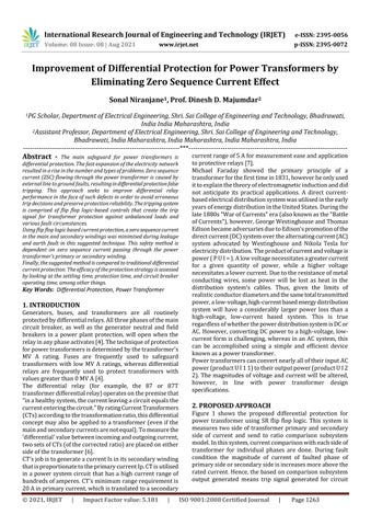
Fig-26: Three phase rms voltage and current of secondary side of transformer during LG (AG) line to ground fault at primary side at 0.8 second simulation time
Advertisement
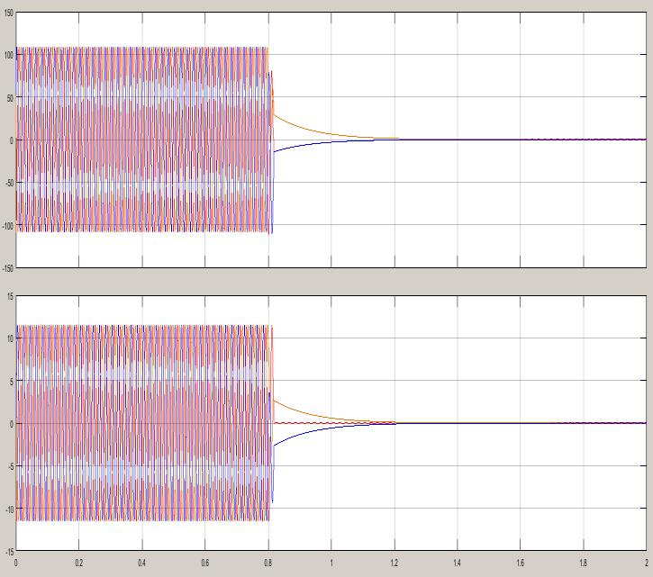
Figure 26 shows that three phase rms voltage and current of secondary side of transformer during LG (AG) line to ground fault at primary side at 0.8 second simulation time. Here it is observe that, when faults occurs at primary winding of transformer in between phase A to ground (LG Fault) at 0.8 second simulation time. Then suddenly after half cycle simulation time circuit breaker open contacts and isolate the primary and secondary side of transformer from three phase source and load. Hence both windings are protecting from faulted short circuit high magnitude current flowing through primary and secondary side of transformer winding. Similarly, figure 27 shows the individual three phases voltages of secondary side of transformer during LG (AG) line to ground fault at secondary side at 0.8 second simulation time. Here it is observe that same condition, with in half cycle after 0.8 second simulation time system voltages of each phases (Va, Vb, Vc) becomes zero due circuit breaker trip operation.
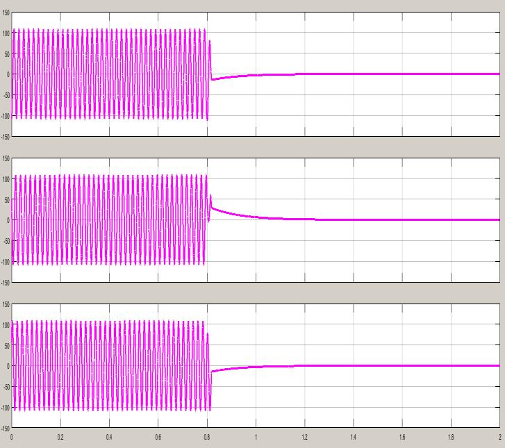
Fig-27: Three phase individual phases voltage of secondary side of transformer during LG (AG line to ground fault at primary side at 0.8 second simulation time. Similarly, figure 28 shows the individual three phases currents of secondary side of transformer during LG (AG) line to ground fault at secondary side at 0.8 second simulation time. Here it is observe that same condition, with in half cycle after 0.8 second simulation time system currents of each phases (Ia, Ib, Ic) becomes zero due circuit breaker trip operation.
Fig-28: Three phase individual phases current of secondary side of transformer during LG (AG) line to ground fault at primary side at 0.8 second simulation time
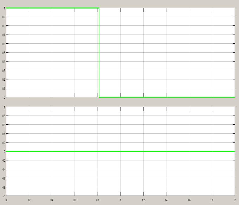
Fig-29: Trip signal generated during case-1 fault at 0.8 second simulation time
Figure 29 shows the Trip signal generated during LG-AG Line to ground fault at primary side at 0.8 second simulation time for circuit breaker operation. The circuit breaker closed their contacts for logic 1 and opens their contacts for logic 0. From figure it is clear that, at 0.8 second simulation time tripping logic is shift from logic1 to logic 0 for circuit breaker contact opening operation. When faults occur at 0.8 second simulation time, there is no any delay for generation of trip signal at 0.8 second. Hence, system becomes very fast to detect the fault condition at secondary sideof transformer.
4. CONCLUSION
The main safeguard for power transformers is differential protection. The fast expansion of the electricity network resulted in a rise in the number and types of problems. Zero
Volume: 08 Issue: 08 | Aug 2021 www.irjet.net p-ISSN: 2395-0072
sequence current (ZSC) flowing through the power transformer is caused by external line to ground faults, resulting in differential protection false tripping. The goal of this research is to improve differential relay performance against such defects such that erroneous trip decisions are avoided and protection reliability is maintained. The suggested algorithm will be used on an 11 KV transmission line with an 11kv/33kv power transformer. It has been discovered that removing ZSC from the differential protection feeling improves differential protection in such circumstances.
The topic of ZSC on transformer differential protection is explored in this study. The factors that influence the ZSC values are also investigated. In addition, due to the presence of the ZSC during external failures, this research provided a novel approach for avoiding the male functioning of the differential protection. During both external and internal failures, the suggested system worked successfully.
REFERENCES
[1] Ismail, A. M., Elghazaly, H., & Emam, A. M. (2019, December). Elimination of Zero Sequence Currents Effect on Differential Protection For Power Transformers Connected to Power Grid. In2019 21st International Middle East Power Systems Conference (MEPCON)(pp. 742-747). IEEE.
[2] Medeiros, R. P., Costa, F. B., & Silva, K. M. (2015). Power transformer differential protection using the boundary discrete wavelet transform.IEEE Transactions on Power Delivery,31(5), 2083-2095.
[3] Balaga, H., Gupta, N., & Vishwakarma, D. N. (2015). GA trained parallel hidden layered ANN based differential protection of three phase power transformer.International Journal of Electrical Power & Energy Systems,67, 286-297.
[4] Guillén, D., Esponda, H., Vázquez, E., & Idárraga-Ospina, G. (2016). Algorithm for transformer differential protection based on wavelet correlation modes.IET Generation, Transmission & Distribution,10(12), 2871-2879.
[5] Murugan, S. K., Simon, S. P., Sundareswaran, K., Nayak, P. S. R., & Padhy, N. P. (2016). An empirical Fourier transformbased power transformer differential protection.IEEE Transactions on Power Delivery,32(1), 209-218.
[6] Sevov, L., Khan, U., & Zhang, Z. (2017). Enhancing power transformer differential protection to improve security and dependability.IEEE Transactions on Industry Applications,53(3), 2642-2649.
[7] Medeiros, R. P., & Costa, F. B. (2017). A wavelet-based transformer differential protection with differential current transformer saturation and cross-country fault detection.IEEE Transactions on Power Delivery,33(2), 789799. [8] Afrasiabi, S., Afrasiabi, M., Parang, B., & Mohammadi, M. (2020). Designing a composite deep learning based differential protection scheme of power transformers.Applied Soft Computing,87, 105975.
[9] Bejmert, D., Kereit, M., Mieske, F., Rebizant,W., Solak, K., & Wiszniewski, A. (2020). Power transformer differential protection with integral approach.International Journal of Electrical Power & Energy Systems,118, 105859.
[10] Esponda, H., Vázquez, E., Andrade, M. A., & Johnson, B. K. (2019). A setting-free differential protection for power transformers based on second central moment.IEEE Transactions on Power Delivery,34(2), 750-759.
[11] Shah, A. M., Bhalja, B. R., Patel, R. M., Bhalja, H., Agarwal, P., Makwana, Y. M., & Malik, O. P. (2020). Quartile Based Differential Protection of Power Transformer.IEEE Transactions on Power Delivery,35(5), 2447-2458.
[12] Power transformer, International Standard IEC 60076, First edition 1997-10.
[13] G. Bertagnolli, “Short-Circuit Duty of Power Transformers; The ABB Approach”, Second Edition, Legnano-Italy, 1996.
[14] Converter Transformers – Application Guide, International Standard IEC 61378-3, First edition 2006-04.
[15] ABB Book, “Transformer Handbook”, 1LAC 000 010, ABB Power Technologies Management Ltd. Transformers, Switzerland.
[16] ABB Leaflet 1LFI2011-en, "Special TransformersConverter Duty Transformers for Variable Speed Drive Application", ABB Oy Transformers, Vaasa, Finland.
[17] ABB Guide, "AC Drives Technical Guide Book", ABB Oy, Drives, (www.abb.com/motors&drives).
[18] R. Grunbaum, M. Noroozian, B. Thorvaldsson, “FACTS –powerful systems for flexible power transmission”, ABB Review No 5, 1999.
[19] A. Sapin, P. Allenbach, J.-J. Simond,“Modeling of MultiWinding Phase Shifting Transformers Applications to DC and Multi-Level VSI Supplies”, PCIM 2002.
[20] H. K. Hoidalen, R. Sporild, “Using Zigzag Transformers with Phase-shift to reduce Harmonics in AC-DC Systems”, International Conference on Power Systems Transients (IPST’05) in Montreal, Canada, June 2005.
[21] L. Asiminoaei, S. Hansen, F. Blaabjerg, “Development of calculation toolbox for harmonic estimation on multi-pulse drives”, IEEE Industry Applications Conference, Vol. 2, pp. 878-885, Oct. 2004.
Volume: 08 Issue: 08 | Aug 2021 www.irjet.net p-ISSN: 2395-0072
[22] P. Bastard, P. Bertrand, M. Meunier “A Transformer Model for Winding Fault Studies”, IEEE Transactions on Power Delivery. Vol. 9. Issue 2, pp. 690-699, April 1994.
[23] Guide for the application, specification, and testing of phase-shifting transformers, International Standard IEC 62032/IEEE C57.135, First edition 2005-03.
[24] K.K. Sen and M.L. Sen, “Introducing the Family of Sen Transformers: A Set of Power Flow Controlling Transformers,” IEEE Trans. Power Delivery, Volume 18, Issue 1, pp. 149-157, Jan 2003.