2 minute read
Three phase transformer

from IRJET- Improvement of Differential Protection for Power Transformers by Eliminating Zero Sequenc

Volume: 08 Issue: 08 | Aug 2021 www.irjet.net p-ISSN: 2395-0072
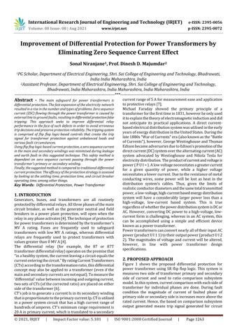
Fig-7: Differential protection subsystem detail model for phase C current comparison
Advertisement
3.2 Model-2: Flip Flop Logic based differential current protection of transformer (One side measurement)
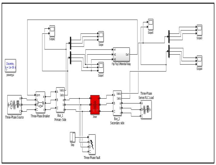
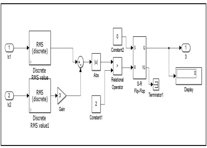
Fig-8: Complete matlab simulation model (model-2) of flip flop differential current protection of power transformer
Table-2: Matlab simulation model-2 parameter specifications
Sr No
Name of simulation block Parameter specification
1. Three phase source
2. Three phase circuit breaker 3. Three phase transformer Phase to phase RMS voltage = 11 KV; Phase angle of phase A = 0 Degree; Supply frequency = 50 Hz; Internal connection = Star connected ground; Three phase short circuit level at base voltage (MVA) = 500 MVA; Base voltage = 11 KV; X/R Ratio = 7 Initial status of breaker = Closed; Breaker resistance = 0.001 Ohm; Snubber resistance Rs = 1 Mega-Ohm; Snubber capacitor Cs = Infinite. Primary winding connection = Star connected with ground; Secondary winding connection = delta; Nominal MVA rating = 500 MVA; 4. Three phase series RLC load
5. Three phase fault Nominal supply frequency = 50 Hz; Primary winding voltage = 11 KV; Secondary winding voltage = 33 KV; Magnetizing resistance Rm = 1.6207 × 10⁶ ohm; Magnetizing inductance Lm = 5158.8 H. Load connections = Star connected with ground; Nominal phase to phase rms voltage Vn = 33 KV; Nominal supply frequency fn = 50 Hz; Active power = 200 MW; Inductive reactive power QL = 100 Var; Capacitive reactive power = 0 Var. Initial status of fault = Open; Faults type possible to simulate = LG, LL, LLG, LLL, LLLG Like AG, BG, CG, AB, BC, AC, ABG, BCG, ACG, ABC, ABCG Fault resistance Rf= 0.001 Ohm; Ground resistance Rg = 0.001 Ohm; Snubber capacitance Cs = Infinite
Figure 8 shows the matlab simulation model of differential current protection of power transformer using SR Flip flop logic. Here, only one end of transformer i.e. either primary side or secondary side three phase rms current is used to measured for protection scheme.
4. SIMULATION RESULTS 4.1 Model-1 Results analysis
Fig-9: Three phase rms voltage and current of primary side of transformer during LLG-ACG Double line to ground fault at primary side at 0.5 second simulation time
Figure 9 shows that three phase rms voltage and current of primary side of transformer during LLG-ACG Double line to ground fault at primary side at 0.5 second simulation time. Here it is observe that, when faults occurs at primary winding of transformer in between phase A and B to ground at 0.5 second simulation time. Then suddenly after half cycle simulation time circuit breaker open contacts and isolate the