2 minute read
Three phase short circuit level at base voltage (MVA) = 500 MVA; Base voltage = 11 KV; X/R Ratio

from IRJET- Improvement of Differential Protection for Power Transformers by Eliminating Zero Sequenc

Volume: 08 Issue: 08 | Aug 2021 www.irjet.net p-ISSN: 2395-0072
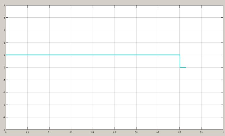
Fig-22: Trip signal generated during LLG-ACG Double line faultat primary side at 0.5 second simulation time for circuit breaker operation
Advertisement
Figure 22shows the Trip signal generated during LG-CG line to ground fault at primary side at 0.8 second simulation time for circuit breaker operation. The circuit breaker closed their contacts for logic 1 and opens their contacts for logic 0. From figure it is clear that, at 0.8 second simulation time tripping logic is shift from logic 1 to logic 0 for circuit breaker contact opening operation. When faults occur at 0.8 second simulation time, there is no any delay for generation of trip signal at 0.8 second. Hence system becomes very fast to detect the fault condition at primary side of transformer.
4.2 Model-2 Results Analysis
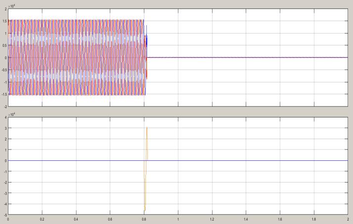
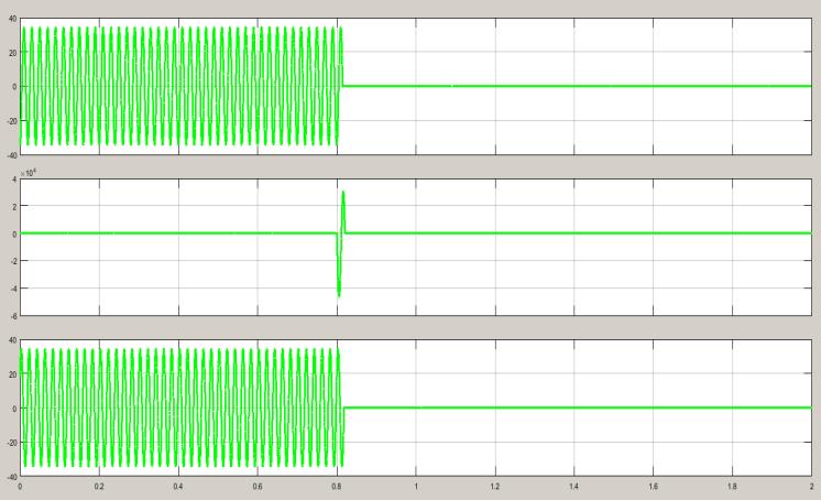
Fig-23: Three phase rms voltage and current of primary side of transformer during LG (AG) line to ground fault at primary side at 0.8 second simulation time
Figure 23shows that three phase rms voltage and current of primary side of transformer during LG (AG) line to ground fault at primary side at 0.8 second simulation time. Here it is observe that, when faults occurs at primary winding of transformer in between phase A to ground (LG Fault) at 0.8 second simulation time. Then suddenly after half cycle simulation time circuit breaker open contacts and isolate the primary and secondary side of transformer from three phase source and load. Hence both windings are protecting from faulted short circuit high magnitude current flowing through primary and secondary side of transformer winding. Fig-24: Three phase individual phases voltage of primary side of transformer during LG (AG) line to ground fault at primary side at 0.8 second simulation time
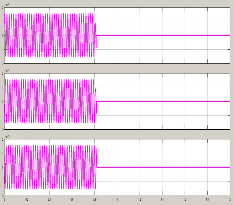
Fig-25: Three phase individual phases current of primary side of transformer during LG (AG) line to groundfault at primary side at 0.8 second simulation time
Similarly, figure 24 shows the individual three phases voltages of primary side of transformer during LG (AG) line to ground fault at secondary side at 0.8 second simulation time. Here it is observe that same condition, with in half cycle after 0.8 second simulation time system voltages of each phases (Va, Vb, Vc) becomes zero due circuit breaker trip operation. Similarly, figure 25 shows the individual three phases currents of primary side of transformerduring LG (AG) line to ground fault at secondary side at 0.8 second simulation time. Here it is observe that same condition, with in half cycle after 0.8 second simulation time system currents of each phases (Ia, Ib, Ic) becomes zero due circuit breaker trip operation.