2 minute read
Lower Cover


Volume: 08 Issue: 06 | June 2021 www.irjet.net p-ISSN: 2395-0072
of Peltier is connected directly to the negative supply of the SMPS of the circuit assembly. The SMPS is further powered by AC power. The two relays Relay1 and Relay2 are mounted on a PCB assembly. The Relay1 is connected to the ATMEGA128P IC via pin 9 and The Relay2 is connected to the ATMEGA128P IC via pin 3. ATMEGA128P IC is further connected to the Bluetooth module HC-05 TX and RXpins which are the transmission and the receiver pins respectively via pins7 and 5 respectively. The PCB assembly is powered via two pins where another SMPS is used to convert 230V AC to 12V DC.
Advertisement
The SMPS for circuit Assembly used is 240W SMPS (ME240W AC input-110V/220V DC Output 12V 20A). This SMPS converts the 230V 50Hz current into 12V 20A current which is used for the Heat Sink fans, Peltier cooler fans and Centrifugal fans. The relays used which are Relay1 and Relay2 are namely used for On and Off switches. These On and Off switches are controlled by ATMEGA128P. The ATMEGA128P is connected to the Bluetooth Module HC-05 it is operated via the android app ‘Bluetooth controller’ in smartphones. The upper button enables the centrifugal fans and they start to operate. The Left button enables the Peltier Modules and the Heat sink fans. The Down button switches the centrifugal fan offand the Right button switches off the Peltier Module and the Heat sink fans.
Fig-13: Bluetooth Controller App.
4. Working
The ATMEGA128P IC is controlled viatheHC-05 Bluetooth Module. The Relays are connected to the ATMEGA128P IC, when the mobile application is operated it transmits the signal to the HC-05 Bluetooth Module. This signal send by HC-05 is sent by ATMEGA128P IC to their respective relays. Whentheupper button is pressed the Relay 2 is operated and then it connects the positive wire of SMPS to the N/O where the positive of the Centrifugal Fans are connected and are then switched ON. Similarly, when Down button is pressed the Relay 1 is operated and it connects the positive wire of the SMPS to the N/O where the positive of the Heat Sink Fans and Peltier modules are connected and is then switched ON. When the Down button is pressed the Relay 2 disconnects the positive wire of the SMPS to the N/O thus the centrifugal fans are switched OFF. When the Right button is pressed the Relay 1 disconnects the positive wire of the SMPS to the N/O thus the Heat Sink Fans and the Peltier modules are disconnected.
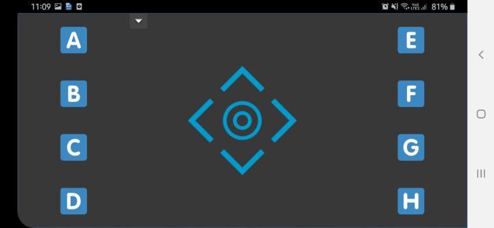
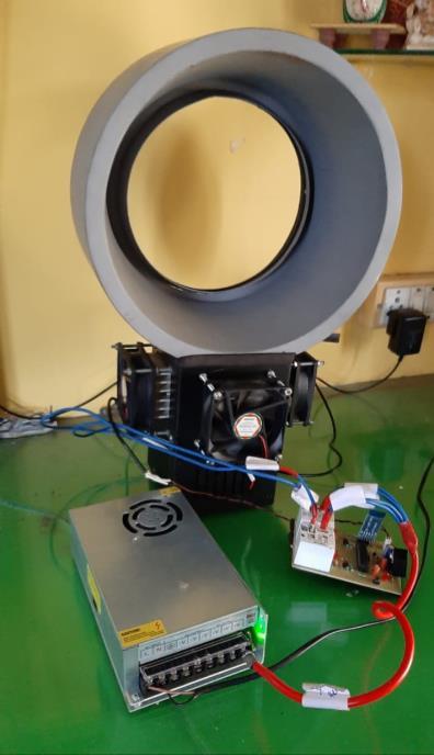
Fig-14: Bladeless fan with a Peltier cooler.
5. Power Calculations and Selection of SMPS.
The power is consumed by the following components in the project.
1.Two Centrifugal Fans. 2.Four Peltier Modules. 3.Four Axial Cooler Fans. 4.One Power Supply to PCB board. Power Consumed by Centrifugal Fans Model: BA10033B12U Vmax= 12V[DC] Imax=2.4A Power=Vmax× Imax =12×2.4 =28.8W For 2 such fans=2×28.8 =57.6W Power Consumed by Peltier Cooler Fans Model:FND-8025-MSC-12D-P Vmax= 12V[DC] Imax=0.18A Power= Vmax× Imax =12×0.18 =2.16W For 4 Fans, Power=4×2.16W =8.64W Power Consumed by Peltier Cooler Fans Imax =4.4A[Value taken from datasheet.] Vmax=14.4V [Value taken from datasheet.]