2 minute read
Hoop Outer Part


Volume: 08 Issue: 06 | June 2021 www.irjet.net p-ISSN: 2395-0072
Recognition of Need.
Advertisement
Deciding the principle of operation of the project.
Make a rough design of the entire project with the arrangement of each component based on the Mechanism of synthesis.
Divide the entire geometry into suitable parts.
Make individual parts on Autodesk Inventor based on like sheet metal and convert the parts into a flat sheet.
arrangement of each component based on the Mechanism of synthesis. Convert the flat sheet parts into .dxf files and Make G and M codes of individual parts of sheet metal.
Give this feed of G and M code to the Laser cutting machine.
Give the cut sheet metal parts to rolling, taper rolling, bending, and welding.
Assemble all the electronic components of the project.
Analyze the project on Ansys.
Test and validate the results.
Optimize the airfoils and find the best shape for a given set of conditions.
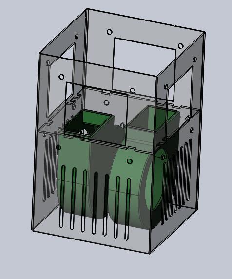
3. ARRANGEMENT OF COMPONENTS
Fig -1: Centrifugal fan(green) assembly at the bottom with the main base.
At the main base frame, two centrifugal fans are placed for proper suction of air into the fan. For suction of the air, vertical ventsare provided at four sides to suck the air into the fan. The trial was taken to use only one centrifugal fan, but since the velocity of air observed was less hence two centrifugal fans are used, to suck more amount of air . The advantage of using centrifugal fans is at very little volume they suck the maximum amount of air. Axial fans require additional space at the bottom of the main base to suck the air, however, a centrifugal fan sucks the air and releases it at the right angle. The centrifugal fans areplaced side by side with their suction side facing in the opposite direction.
Fig-2: Cold Chanber Box(blue) mounted on the main base with centrifugal fan(green).
The air after suction from the bottom part then moves over the aluminium box (shown in blue) placed above it. The outlet of centrifugal fans is covered with an aluminium plate. This aluminium box act as the cold chamber of the project. Each of the four vertical sides of the aluminium box is in physical contact with the cold sides of the four Peltier modules used. Aluminium box is used as a material other than Mild steel because of its high thermal conductivity (thermal conductivity of aluminium box, k= 205W/mK). Materials with high thermal conductivity have very little resistance and obtain heatvery quickly as a result heat can pass easily through them. Aluminium thermal conductivity is