3 minute read
Hoop Front Part


Volume: 08 Issue: 06 | June 2021 www.irjet.net p-ISSN: 2395-0072
3.5 Electrical Circuit.
Advertisement
3.5.1 Electrical Components
The assembled Hoop with Main Base andAluminium Box is then assembled with Peltier module. The cold side of the Peltier module is matted to the aluminium box through the slot left in the main base. Peltier module with written TEC12706 is the cold side. The fins are in contact to the hot side. In between the connection with the Peltier module with the metal a thermal paste is used. Thermal paste ensures the proper dissipation of heat between two surface and there are no irregularities which form thermal resistance. Inorder to increase the heattransfer rate, the hot side is joined to the fans. The fans with their suction at the outerside is used. The fan is assembled to the fins using a screw joint. Thus, electric components are mounted on the bladeless fan.
3.5.2 Electrical Connection Connection.
The electrical part consists of the following components: 1. Heat Sink Fans(Model BS10033812U) 2. Peltier Module(TEC1-12706) 3. Centrifugal Fans(FND-8025-MSC-12D-P) 4. PCB Assembly. 5. SMPS for Circuit Assembly 6. SMPS for PCB.
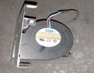
1.Heat Sink Fans (Model BS10033812U):These fans are used to cool the hot side of the Peltier modules. The hot side of the Peltier modules is first connected to the fins, just outside the fins these fans are used. These fans are DC Brushless fans that use the forced convection air to cool the fins at a faster rate. 2.Peltier Module (TEC1-12706):These are 12V, 6A Peltier modules when the current flows there is a formation of a hot side and a cold side. The cold side of the Peltier. The module is connected Aluminium Box through which air will be passing. The hot side of the Peltier cooler is connected to the fins which are connected to the Brushless DC fans which are used for cooling purposes. The side with TEC1-12706 is written inthe cold side and the oppositeside is the hot side. 3. Centrifugal Fans (FND-8025-MSC-12D-P): These fans are used to suck the air inside. As centrifugal fan suction and delivery are at right angles this unique property makes them suitable for this application. The mounting of centrifugal fan is done using a screw.
Fig-10: Centrifugal fan mounted on Aluminium Cover. 4. PCB Assembly:The PCB Assembly consists of two relays Relay1 and Relay2, ATMEGA128P IC, HC-05 Bluetooth Module, 7805 Regulator, and other electrical components like resistors, capacitor, etc. The PCB assembly is custom designed for this circuit in the project.
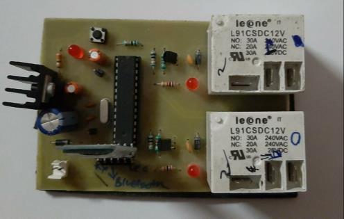
Fig-11: PCB components assembly.
5. SMPS for Circuit Assembly: The SMPS is used for the centrifugal blowers, Peltier module and the axial flow fans. This SMPSis 12V/20A, which converts 230V 50Hz AC power to 12V/20A DC. The selection of the SMPS is done based on the power consumption. 6. SMPS for PCB:This circuit is powered by SMPS which is given AC power supply. SMPS converts the AC powersource into DC whichis required by the PCB assembly.
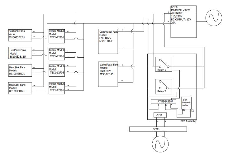
Fig-12: Electrical Circuit Connection Layout.
Heat Sink Fans(Model BS10033812U) are DC-Brushless fans requiring 12V and 0.18A which are used to cool the hot side of the fins of the Peltier module. Four such fans are used with each fan connected to each hot side of the Peltier modules. Peltier Module (TEC-12706) which require maximum 12 V and 6A are used for cooling purpose. All the positive wires of the four Heat Sink Fans and the positive of the four Peltier Modules are connected. This connection is further extended to the N/O of the Relay1. Relay 1 used is L91CSDC12V Relay it supports N/O current up to 30A and N/C current up to 20A. Two Centrifugal fans(FND-8025-MSC-12D-P) are also used to suck the air. The positive of these two centrifugal fans are connected to N/O of Relay 2. Relay 2 used is L91CSDC12V which is same as the Relay1. The negative wires of two centrifugal fans are connected and connected with the negative of all the Heat Sink Fans and the negative