International Research Journal of Engineering and Technology (IRJET) Volume: 08 Issue: 05 | May 2021
www.irjet.net
e-ISSN: 2395-0056 p-ISSN: 2395-0072
Case Study on Design and Analysis of Worm Gear Box for Elevator Divij Pharkute1, Varad Pimple2, Piyush Khandekar3, Akshata Pokharkar4, Parimal Phanse5 1-5Student
of Vishwakarma Institute of Technology, Pune, Maharashtra, India
---------------------------------------------------------------------***--------------------------------------------------------------------2. THEORY
Abstract - Elevator is the device which is used to transfer
Application of elevator-
people on different floors in a building, for doing so they use electric motors and worm gear box. A worm gear box consists of a worm gear & worm wheel. The input of the motor is given to the worm gear which in turn drives the worm wheel, to which pulley is attached. Worm gears are most suitable for transmitting power between two shafts that are perpendicular but not intersecting. They are mainly used for this application because of high speed reduction ratio. In this paper, worm gear box is designed for 6 passengers & FEA analysis is doneby applying different forces on worm gear and wheel. Structural was performed in ANSYS software while the Modelling was done on Solidworks.
An elevator's function is to convert the initial electrical power, which runs the motor, into mechanical power, which can be used by the system. The elevator is composed of a motor and, most commonly, a worm gear reducer system. A worm gear system is made up of a worm gear, typicallycalled the worm, and a larger round gear, typically called the worm gear. These two gears which have rotational axes perpendicular to each other, not only decrease the rotational speed of the traction pulley, but also change the plane of rotation. By decreasing the rotation speed, with the use of a gear reducer, we are also increasing the output torque, therefore, having the ability to lift larger objects for a given pulley diameter. A worm gear is chosen over other types of gearing possibilities because of its compactness andits ability to withstand higher shock loads. It is also easily attached to the motor shaft, sometimes through use of a coupling. The Figure 1: Worm and Worm Wheel3 gear reduction ratios typically vary between 12:1 and 30:1. The motor component of the elevator machine can be either a DC motor or an AC motor. An AC motor is more regularly used because of its ruggedness and simplicity. A motor is chosen depending on design intent for the elevator. Power required to start the car in motion is equal to the power to overcome static, or stationary friction, and to accelerate the mass from rest tofull speed.
Key Words: Elevator, worm gear box, high speed reduction, ANSYS, solidworks.
1. INTRODUCTION A worm gear (or worm drive) is a specific gear composition in which a screw (worm) meshes with a gear/wheel similar to a spur gear. The set-up allows the user to determine rotational speed and also allows for higher torque to be transmitted. An electric motor or engine applies rotational power via to the worm. The worm rotates against the wheel, and the screw face pushes on the teeth of the wheel. The wheel is pushed against the load. Applications - Lifting Devices, Cranes, Elevators, Belt conveyors etc.
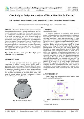
3. METHODOLOGY Worm & worm gear Terminology A pair of Worm & worm gear is specified & designated as – z1/ z2/q/m
Fig -2: Terminology of Worm and Worm Whee Where,
Fig -1: Worm and Worm Wheel
z1 = no. of start on worm
© 2021, IRJET
|
Impact Factor value: 7.529
|
ISO 9001:2008 Certified Journal
|
Page 3631