International Research Journal of Engineering and Technology (IRJET)
e-ISSN: 2395-0056
Volume: 08 Issue: 02 | Feb 2021
p-ISSN: 2395-0072
www.irjet.net
COMPARATIVE STUDY OF MULTI LEVEL INVERTERS BASED ON THE OUTPUT TOTAL HARMONIC DISTORTION Binny Sharma1, Ravinder Kaur Randhawa 2 1PG
student, Department of Electrical Engineering, Guru Nanak Dev Engineering college, Ludhiana, India Professor, Department of Electrical Engineering, Guru Nanak Dev Engineering college, Ludhiana, India ---------------------------------------------------------------------***--------------------------------------------------------------------2Assistant
Abstract - The power converters are utilized to change one
sinusoidal waveform is produced at the output voltage and harmonics inside the output can be suppressed and percentage of losses may be decreased and this topology is named as multilevel inverter topology. The multilevel inverter topology concept has been introduced in the early 1975 with three level converters. Multi-level inverters are widely used as stationary power converters for very highpower operations such as FACTS devices, HVDC light transmission and AC drives. One of the powerful benefits of multi-level modeling is the minimal harmonic in the output waveform without reducing the inverter power output and controlling the speed of a single-phase induction motor for low dissipation of electrical energy. Thus, the inverter is known as a multi-level inverter that starts at 3-levels and as the number of levels of the inverter increases, the total harmonic distortion (THD) decreases.
type of electrical energy to another. The class of power converter that produce AC power from DC power is known as inverter. Because of high THD and losses, the conventional two-level inverters are not appropriate for high power applications. So multilevel inverters have attracted huge significance power industries. This thesis presents different types of multilevel inverters and their significances. In this work three cases of power electronic inverters are taken into consideration for comparison to analyses the performance in terms of total harmonic distortion in their output voltage and output current. A 5 and 7 level H-bridge inverter is simulated with SPWM technique to generate the gating pulses for the switches. The same switching techniques are used for 5 and 7 level Flying Capacitor Type inverter and Diode Clamped Inverter is designed. The FFT analysis is performed to understand the total harmonic distortion of output current and output voltage of all the three cases. A comparison study is made between all the three inverters total harmonic distortion of their output current and output voltage by keeping the load resistance and inductor value as constant and vice versa.
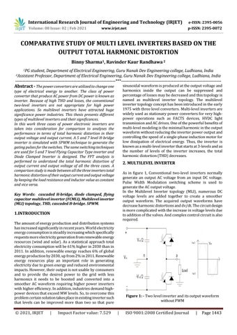
2. MULTILEVEL INVERTER As in figure 1, Conventional two-level inverters normally generate an output AC voltage from an input DC voltage. Pulse Width Modulation switching scheme is used to generate the AC output voltage. In the Multilevel Inverter topology (MLI), numerous DC voltage levels are added together to create a smoother output waveform. The acquired output waveforms have decrease harmonic distortions and dv/dt. The circuit design is more complicated with the increase in voltage levels due to addition of the valves. And complex control circuit is also required.
Key Words: cascaded H-bridge, diode clamped, flying capacitor multilevel inverter (FCMLI), Multilevel inverter (MLI) topology, THD, cascaded H-bridge. SPWM.
1.INTRODUCTION The amount of energy production and distribution systems has increased significantly in recent years. World electricity energy consumption is steadily increasing which specifically requests more electricity generation from renewable energy resources (wind and solar). As a statistical approach total electricity consumption will be 61% higher in 2030 than in 2011. In addition, renewable energy reaches 6% of global energy production by 2030, up from 2% in 2011. Renewable energy resources play an important role in generating electricity due to green energy and reduced environmental impacts. However, their output is not usable by consumers and to provide the desired power to the grid with less harmonics it needs to be boosted and converted into a smoother AC waveform requiring higher power inverters with higher efficiency. In addition, industries demand highpower devices that exceed MW levels. So, to overcome this problem certain solution takes place in existing inverter such that levels can be improved more than two so that pure
© 2021, IRJET
|
Impact Factor value: 7.529
Figure 1: - Two level inverter and its output waveform without PWM
|
ISO 9001:2008 Certified Journal
|
Page 1443
