to extract more information than is shown in the original image. It is an integral part of the applications used in publishing, satellite imagery analysis, medical fields, earthquakes, and many different fields. Images are often problematic with high level components of noises. Image denoising is the technique of removing various types of noises or distortions from the corrupted image while retaining the edges and other features as detailed as possible. To achieve this goal, it makes use of a mathematical function known as the wavelet transform. Wavelet transform has unique advantages when it comes to working with a single point, but has some disadvantages when it comes to working with the borders and the line features of an image. There was also a Ridgelet transform that could only represent images of line singularities in two dimensional space and not the curve singularity. For better representations of images with curve singularities in high dimensions, a Curvelet transform was introduced An image's edges can be represented in a very useful way with the Curvelet transform since it is anisotropic with strong directional characteristics. The objective of this research is to analyze the wavelet, ridgelet, and curvelet transformfor removingmultipletypes ofnoise fromanimage and determiningthemostappropriatetransformamongthem.
Abstract Image processingreferstodigitalimageprocessing
Binary image Image where pixels have either a valueof0(dark)or255(bright).
Fig 1:DifferenttypesofImages
Key Words: Wavelet transform, Ridgelet transform, CurveletTransform,Denoising,MATLAB
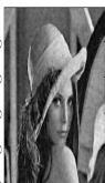
An image is a multidimensional array of numbers between 0 and 255, known as pixels. Each number is identified by a combination of horizontal and vertical coordinates.ThreedifferenttypesofImages
Grayscaleimage Thegrayscaleimagehasapixel valuerangingfrom0to255.
ImageProcessingisatypeofsignalprocessinginwhich inputisanimageandoutputmaybeeitheranimageorthe characteristics and features associated with it. It enables someoperationstobeperformedonanimage,toenhanceit, or to extract some useful information from it Image Processingtechniquesarerequiredinthefieldofresearch andtechnology. Image processingis a veryimportantand basetechnologyformanyreal timeapplicationslikeimage search engines, image clustering, image segmentation, Entropy detection, etc. Image clarity is an important propertyofimageandthemaximumpercentageisexpected for image processing applications. The accuracy of image processing results is determined by this factor. The increased level of clarity will increase the result accuracy dramaticallyandalsomakestheresultsreliable.All natural phenomena and transmission errors are degrading the imagequalitytherebynoiseisintroducedintheimage.
1. INTRODUCTION
International Research Journal of Engineering and Technology (IRJET) e ISSN: 2395 0056 Volume: 08 Issue: 12 | Dec 2021 www.irjet.net p ISSN: 2395 0072 © 2021, IRJET | Impact Factor value: 7.529 | ISO 9001:2008 Certified Journal | Page1066 ANALYSIS OF WAVELET, RIDGELET AND CURVELET TRANSFORMS ON IMAGE DENOISING Susmitha Gurram1 , Uday Bheem Sai Chagantipati2
2Programmer Analyst at Cognizant Technology Solutions, B.Tech in Dept. of Electronics and Communication Engineering, JNTUH College of Engineering Sultanpur, Telangana, India ***
ColorImage GrayscaleImage BinaryImage
The wavelet, ridgelet, and curvelet transform for image denoising are implemented using Matlab. We analyze the accuracy, scalability, and graphical representation of image denoising based on wavelets, Ridgelets, and Curvelets.
Imageblurrinessisacommonproblemintheareaofimage processing, which is also called a noisy image noise, often referredtoas"noiseinpictures,"isavariationinbrightness orcolorinformationincorporatedintoimages,obscuringthe desired information. During transmission, acquisition, coding, and processing steps, noise is introduced into the image.Noisemodelsinvolvedareasfollows: Additive Noise The process of adding noise to youroriginalimageresultsinanoisyimagethatis corrupted.
1Student, Dept. of Electronics and Communication Engineering, JNTUH College of Engineering Hyderabad, Telangana, India
Color image The color image is composed of 3 channelsred(R),green(G),andblue(B).Eachpixel valueisbetween0and255.


C(x,y)=O(x,y)*N(x,y) C(x,y)=CorruptedNoisyImage;O(x,y)=OriginalImage; N(x,y)=ImageNoise; Thereisaneedforimagedenoisingtoreducethenoise level present in the image to produce the denoised image that is nearer to the original image Image denoising is a qualityenhancementmethodinimageprocessing,wherethe noise is removed from the noisy image and recovers the originalimagebyretainingitsquality,whichgetscorrupted duringitsacquisitionortransmission Therearemanyfields of image processing that depend on denoising to recover anatomicaldetailsthatmayhavebeenmaskedinthedata duetodifferenttypesofnoise.Edgepreservationneedstobe balancedwithdenoisingsinceedgesarethemostimportant aspect of biomedical images and other field images. As a result,thehigh frequencycomponentofthenoisyimageis filteredwhilethelow frequencyinformationisleftintact.In this paper, Image denoising is done based on Wavelet, Ridgelet,andCurvelettransformstoobtainthebestresults byremovingthedifferenttypesofnoisefromnoisyimages
C(x,y)=O(x,y)+N(x,y) Multiplicative Noise Inthiscase,theimagenoise is multiplied by the original image, resulting in a corruptednoisyimage.
2. PROPOSED METHODOLOGY Intheproposedpaper,thewavelet,ridgelet,andcurvelet transforms are compared to determine the best one for removing noise from images to retain the features and qualityoftheoriginalimage.
Fig 2:FlowChartofImageDenoisingusingTransform 2.1 Different Types of Noises A) Gaussian Noise In mathematical terms, it is statistical noise with a probability density function (PDF) equal to the Normal Distribution.
SourcesofGaussianNoise DuringImageAcquisition Example Due to poor illumination and high temperatures,thereissensornoise. During ExampleTransmission.Electroniccircuitnoise.
International Research Journal of Engineering and Technology (IRJET) e ISSN: 2395 0056 Volume: 08 Issue: 12 | Dec 2021 www.irjet.net p ISSN: 2395 0072 © 2021, IRJET | Impact Factor value: 7.529 | ISO 9001:2008 Certified Journal | Page1067
Fig -3:Gaussianfunction Fig 4:Gaussiannoise B) Salt and Pepper Noise ItisalsocalledDatadrop out. ItisafixedvaluedImpulseNoise.Theresultsforan 8 bit image are 255 (bright) for salt noise and 0 (dark)forpeppernoise. SourcesofSaltandPepperNoise Sharp and sudden disturbances in the image signal. Malfunctioningofcamera’ssensorcell. Theprobabilitydensityfunction‘S’isgivenby:


Fig 5:SaltandPeppernoise
Effectofenvironmentalconditionsduringimaging sensorintheprocessofimagetransmission. Specklenoisefollowsgammadistributionasfollows: Fig 6:Specklenoise D) Poisson Noise ItcanalsobereferredtoasQuantum(Photon)NoiseorShot
Fig 8:ImageDenoising
To convert an image from one domain to another, an image transform can be applied. Processing an image in a nonspatial domain such as frequency makes it possible to identifyfeaturesthatmayotherwisebedifficulttoidentifyin thespatialdomain.
One of the most famous image analysis tools is the wavelettransform Afeatureofthisistheabilitytolocalize "point singularities" in the image as a result of its advantageousproperties. Animageisrepresentedusingthe Discrete Wavelet Transform as a series of approximate coefficientsanddetailedcoefficientsatdifferentresolutions. Whenanimageisfilteredfromahigherresolutiontoalower resolution, high pass filtration gives approximation coefficients, while low pass filtration gives detailed coefficients.Waveletrepresentationscontainasetofdetail
Randomfluctuationofphotons. Fig 7:Poissonnoise 2.2 Image Denoising
Imagetransformsinclude: WaveletTransform RidgeletTransform CurveletTransform A) Wavelet Transform
C) Speckle Noise Animagecanbecorruptedbyspecklenoise,whichisa noisemultiplroughnoisethatnaturallyexists.Randompixelvaluescanbeiedwithdifferentpixelsinanimagetomodelspeckle.SourcesofSpeckleNoise
2.3 Image Transforms
International Research Journal of Engineering and Technology (IRJET) e ISSN: 2395 0056 Volume: 08 Issue: 12 | Dec 2021 www.irjet.net p ISSN: 2395 0072 © 2021, IRJET | Impact Factor value: 7.529 | ISO 9001:2008 Certified Journal | Page1068
Thetechniqueofimagedenoisingistheremovalofnoise fromanoisyimagesothataclearimagecanbeobtained.Itis hardtodistinguishnoise,edges,andtexturesintheprocess ofdenoising,andthedenoisedimagesarelikelytolosesome details. Today, a significant challenge in obtaining high qualityimagesthroughthenoiseremovalprocesstorecover meaningful information from noisy images. An image is preservedinitsdetails,whilethedifferenttypesofnoiseare removed as much as possible This process involves reconstructinganimagefromanoisyone. Akeyobjectiveofimagedenoisingistoremovenoiseand retainusefulinformationabouttheimage Generally,anoisy image is applied with the image transform to obtain a denoisedimagebyremovingthedifferenttypesofnoisesin anImageimage.withnoise DenoisedImage
Noise The noise of this type has a Poisson distribution probabilitydensityfunction. SourcesofSaltandPepperNoise


Fig 11:FlowchartofDiscreteRidgeletTransform
coefficients at all resolutions and an approximation coefficientat resolution.
thelowest
Themainthemeofwavelettransforms: The time domain does not provide frequency information
The2 DcontinuousRidgelettransforminthesquareofR canbedefinedbythefollowingbasisfunction: aWhere,Scaleoftheridgelets;θ Orientation;b Location; Foreacha>0,b∈Randθ∈(0,2π)
International Research Journal of Engineering and Technology (IRJET) e ISSN: 2395 0056 Volume: 08 Issue: 12 | Dec 2021 www.irjet.net p ISSN: 2395 0072 © 2021, IRJET | Impact Factor value: 7.529 | ISO 9001:2008 Certified Journal | Page1069
Fig -9:Blockdiagramforthewavelettransform Waveletsoscillatelikewavesbutarequicklyattenuated. Anadmissibilityconditionforawaveletisthatitisafunction ψofthesquareofL(R): Wavelet coefficients are obtained by decomposing a noisyimagewiththediscretewavelettransform Byusing waveletthresholding,thewaveletcoefficientsaredenoised. To denoise the images, the modified coefficients are subjectedtotheinversediscretewavelettransform.
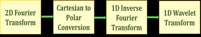
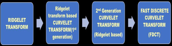
The Fourier transform does not include time information Fig 10:Thedifferencebetween waveletandcurveletin sparseapproximation B) Ridgelet Transform Ridgelettransformisadenserepresentationoffunctions with discontinuities along lines that arises from a need to find a sparse representation Ridgelet transform is used because the wavelet transforms only work for point discontinuitiesin1Dwhilefailingwhenappliedtoedgesin 2D.Edgesin2 DarenotbetterrepresentedbytheRidgelet transformthanbythewavelettransform. Ridgelettransformisapowerfultoolforextractinglines from edge dominated images. Radon transform facilitates the implementation of Ridgelet, which achieves a very compactrepresentationoflinearsingularities.Inthisway, theyareparticularlyimportantfromavisualpointofview, since they can significantly contribute to detecting and representing.IntheRadon domain, it can be conceptualized as a waveletanalysisappliedtotheRidgeletdomain.TheRadon transformisashapedetectiontool.TheRidgelettransform belongstoafamilyofdiscretetransformsthatemploybasis functions.Inessence,theRidgelettransformcanbeusedasa tooltodetecttheridgesorshapesofobjectsinanimage,as well as to make the detection of ridges or shapes easier. Recently,ithasbecomeanalternativemethodtoovercome problemswithwavelettransforms.A2Dwavelettransform produces large wavelet coefficients at every scale of decomposition. Since the Ridgelet transform has so many largecoefficients,de noisingofnoisyimagesisdifficult,so de noisingofnoisyimageswithanefficientlegacywavelet mechanism becomes problematic. Ridgelet transform was successfully used to process digital images with different orientationsandlocations Theridgelettransformcalculates integralsbasedonthedata'sorientationandlocationbefore processingit.Aridgeletisconstantalongthelinesx1cosβ+ x2 sin β = constant. In the direction orthogonal to these ridgesitisawavelet.De noisingimagesusingridgeletshas recentlybeensuccessful.


Convert the Fourier transform from cartesian to polarformusinganinterpolationscheme.Thatis, putthesampledvaluesfonthepolarlatticeinstead ofthesampledvaluesfonasquarelattice
Thus,theRidgeletcoefficientsarerepresentedby: Thereconstructionformulaisgivenby: TheRadontransformofanobjectisgivenby: TheRidgelettransformcanberepresentedasfollows: Ridgelet transforms are applied to slices of Radon transformswhereangularvalue‘θ’remainsconstantwhile the angular value 't' varies. The approximate Radon transforms can be computed from discrete fast Fourier transformsasfollows:
It is one of the main disadvantages of wavelet transformations in image processing that the two dimensionalwavelettransformgivesanenormousnumber ofcoefficientscorrespondingtotheimageedges.Moreover, the reconstruction of these edges is difficult, and many coefficientsarerequired.RecentapproacheslikeRidgelets and Curvelets exploit this fact by exploiting the fact that wavelets are good only for point singularities and are not efficient to handle linear or curvilinear singularities in an image Curvelet transforms are characterized by their sparsityandtheabilitytorenderedgesorsingularities
transformTocalculatethecontinuousridgelettransform,theRadonRf (θ, t) is first computed by computing the inverse Fourier transform applied to the two dimensional Fourier transform restricted to radial lines through the origin,andtheone dimensionalwavelettransformisapplied totheseslices.TheRadontransformisobtainedbyapplying theinverseFouriertransformtothetwo dimensionalFourier transformrestrictedtoradiallinesthroughtheorigin.
The subbands are divided into small squares throughsmoothpartitioning.
International Research Journal of Engineering and Technology (IRJET) e ISSN: 2395 0056 Volume: 08 Issue: 12 | Dec 2021 www.irjet.net p ISSN: 2395 0072 © 2021, IRJET | Impact Factor value: 7.529 | ISO 9001:2008 Certified Journal | Page1070
Computetheone dimensionalInverseFastFourier Transform (IFFT) for each line that is for each angularparameterofeachline
Fig -12:FlowchartsofRidgeletTransform C) Curvelet Transform
Followingarethestepsofcurveletanalysis: In the subband decomposition process, a bank of filters is applied to break down the image into dyadicscales
waycharacteristics,idealdisadvantages.istransform,directionality,havethreeseriousdrawbacks:shiftsensitivity,poorandnophaseinformationTheCurveletwhichhasahighdegreeofdirectionalspecificity,proposedasamethodthatovercomestheseItisdifficulttodesigncomplexwaveletswithreconstructionpropertiesandgoodfilterthoughthecomplexwavelettransformisonetoimprovedirectionalselectivity
Thediscreteridgelettransformisusedtoanalyze each Comparedsquaretotraditional wavelets, curvelet transforms are much more efficient at representing edges and curve singularities. Wavelets have the disadvantage of poor directionality.DWTsarepowerfultoolsinimageprocessing, butthey
Perform the two dimensional Fast Fourier Transform(FFT)ofthe'f'function.


3. EXPERIMENTAL RESULTS AND DISCUSSIONS
Generalized Curvelet Transform can be described as follows:Becausecurvelettransformsaretypicallyappliedinthe frequencydomain,theaboveequationcanbeexpressedas: CurveletTransform=IFFT{FFT(Curvelet)xFFT(Image)} Curveletsinthespatialdomainarearrangedinvarious orientations(θ)andScale(j)(Coarsertofiner)insuchaway thattheentireFFTplaneiscoveredtoavoidanysignalloss. In the figure, 5 level curvelet digital tiling of an image is shownalongwithFFTofacurvelet(shadedwedge)atscale 4andorientation4.Approximationcoefficientsareshownin the center square (at scale 1), while Detailed Curvelet coefficients are shown in the other wedges at scales j=2,3,4,5,andsoon.AtScale2,thereare16possiblecurvelet orientations. On scale 3, 32, and scale 4, there are 32 orientationsandsoon. In the comparison of wavelet, ridgelet and curvelet transformforremovingthedifferenttypesofnoisesfroman image, the best transform among the three transforms is obtained. Fig 15:5 levelcurveletdigitaltilingofanimageisshown alongwithFFTofacurvelet(shadedwedge)atscale4and orientation4
Theresultsforremovingdifferenttypesofnoisesfrom the images using wavelet transform along with its SNR valuesareshowninthetable
International Research Journal of Engineering and Technology (IRJET) e ISSN: 2395 0056 Volume: 08 Issue: 12 | Dec 2021 www.irjet.net p ISSN: 2395 0072 © 2021, IRJET | Impact Factor value: 7.529 | ISO 9001:2008 Certified Journal | Page1071 Fig 13:CurveletTransform
The different types of noise from images are removed usingthreetransformsinthispaper.MATLABsoftwarewas used to process the image and remove noises of various types.TheSignaltoNoiseRatio(SNR)valuesoftheoriginal inputimageswiththeirnoisyimageandthedenoisedimage iscalculatedtodeterminethebesttransformamongwavelet, ridgelet,andcurvelettransforms Denoisingtheimageshas been achieved by using wavelet, ridgelet, and curvelet transforms.ItshowsthatbetterSNRvaluesdeterminethe best transform among the three The improvement in performanceparametersvaluesobtainsthebesttransform thatcaneffectivelyremovethedifferenttypesofnoisesfrom the images To compare the performance of each of these transformationsonimages,wetakedifferenttypesofimages andadddifferenttypesofnoisestoanimageandnotethe SNRvaluestodeterminethebesttransformamongthem.
Fig 14:StagesofconversionfromRidgeletTransformto CurveletTransform Anefficientmethodforsolvingpartialdifferentialequations (PDEs), image processing, fluid mechanics, and Partial differential equations(PGEs) is the Second Generation Curvelet Transform. There are many problems associated with it, such as high redundancy and poor sparse approximationofcurvefeaturesbeyondC2 singularities. To implement the newly implemented curvelet transform,alsoknownasFDCT,therearetwoways: UnequallySpacedFastFourierTransform(USFFT) Wrappingfunction. Wrapping based FDCT is faster than USFFT, therefore wrapping basedFDCTiswidelyused


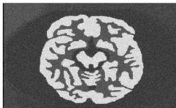
International Research Journal of Engineering and Technology (IRJET) e ISSN: 2395 0056 Volume: 08 Issue: 12 | Dec 2021 www.irjet.net p ISSN: 2395 0072 © 2021, IRJET | Impact Factor value: 7.529 | ISO 9001:2008 Certified Journal | Page1072 Table -1: Wavelettransformresults Thus,wecannowcomparethewavelettransformresults totheothertransformsbycomparingtheSNRvalues. Theresultsforremovingdifferenttypesofnoisesfrom the images using Ridgelet transform along with its SNR valuesareshowninthebelowtable. Table 2: Ridgelettransformresult Theresultsforremovingdifferenttypesofnoisesfrom the images using Curvelet transform along with its SNR valuesareshowninthebelowtable. Table 3: Curvelettransformresults TYPE OF IMAGE TYPE OF NOISE SNR IMAGENOISYLORIGINAVS SNR DDENOISELORIGINAVSIMAGE X Ray GAUSSIAN 16.7167 24.5096 POISSON 22.0291 27.3503 RANDOM 15.2139 15.2380 SALT & PEPPER 17.4552 17.5905 SPECKLE 13.9162 15.7889 Cameraman GAUSSIAN 17.7122 22.9596 POISSON 21.8056 23.9154 RANDOM 16.4904 22.3245 SALT & PEPPER 19.3795 19.5030 SPECKLE 13.0491 19.1355 Lena GAUSSIAN 20.8279 25.1971 POISSON 20.8279 27.5101 RANDOM 13.8260 13.9703 SALT & PEPPER 16.4820 16.8714 SPECKLE 13.1553 17.4107 Womenandbaby GAUSSIAN 19.1847 30.0657 POISSON 22.5356 30.9337 RANDOM 18.0668 18.0765 SALT & PEPPER 20.7693 20.9552 SPECKLE 13.7627 21.8921 Building GAUSSIAN 19.3592 26.6154 POISSON 22.6225 26.7079 RANDOM 18.4168 26.2133 SALT & PEPPER 21.0088 21.3765 SPECKLE 13.7887 21.9778 MRI Spine GAUSSIAN 14.3754 21.6094 POISSON 21.2729 24.1396 RANDOM 13.1690 21.1571 SALT & PEPPER 15.4106 15.8091 SPECKLE 13.9668 15.6001 TYPE OF IMAGE TYPE NOISEOF SNR IMAGENOISYLORIGINAVS SNR IMAGEDENOISEDVSORIGINAL X Ray NGAUSSIA 15.7167 22.5096 POISSON 201466 256381 MRANDO 131591 13.2619 SALT PEPPER& 19.5251 19.6150 SPECKLE 117534 178462 X Ray NGAUSSIA 137284 259265 POISSON 201466 256381 MRANDO 13.1591 13.2619 SALT PEPPER& 195251 196150 SPECKLE 11.7534 17.8462


[3] M.N.DoandM.Vetterli,"Thefiniteridgelettransform for image representation," in IEEE Transactions on Image Processing, vol. 12, no. 1, pp. 16 28, Jan. 2003, doi:10.1109/TIP.2002.806252.
[4] H. Li, S. Wang and C. Deng, "New Image Denoising MethodBasedWaveletandCurveletTransform,"2009 WASE International Conference on Information Engineering, 2009, pp. 136 139, doi: 10.1109/ ICIE.2009.228.
[2] S. Zhen gang and L. Qin zi, "Pulmonary CT image denoising algorithm based on curvelet transform criterion,"20177thIEEEInternationalSymposiumon Microwave, Antenna, Propagation, and EMC Technologies (MAPE), 2017, pp. 520 524, doi: 10.1109/MAPE.2017.8250909.
4. CONCLUSIONS Thispaperpresentsananalysisofwavelet,ridgelet,and curvelet transforms for image denoising. Using these transforms,differenttypesofnoisesfromanimagecanbe removedfromit,therebyimprovingitsquality.Intermsof performanceaswellasvisualquality,theresultsobtained fromtheactualimagesalongwiththeSNRvaluesconcluded thatthecurvelettransformwasthebestsolutiontoremove thedifferenttypesofnoiseinanimage.
International Research Journal of Engineering and Technology (IRJET) e ISSN: 2395 0056 Volume: 08 Issue: 12 | Dec 2021 www.irjet.net p ISSN: 2395 0072 © 2021, IRJET | Impact Factor value: 7.529 | ISO 9001:2008 Certified Journal | Page1073
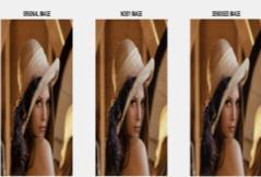
OriginalImage NoisyImage Wavelet Ridgelet Curvelet Fig 16:Original,Noisy,andDenoisedimagesusing wavelet,ridgelet,andcurvelettransforms. We can therefore conclude by looking into the output imagesandtheirSNRvaluesthatthecurvelettransformis the best among the three transforms for removing the differenttypesofnoise.
REFERENCES [1] N. Mittal, A. Raj and H. Goyal, "Enhancement and Removal of Noise from Medical Images by Wavelet TransformMethod,"20193rdInternationalconference on Electronics, Communication and Aerospace Technology (ICECA), 2019, pp. 1126 1130, doi: 10.1109/ICECA.2019.8821979.