International Research Journal of Engineering and Technology (IRJET)
e-ISSN: 2395-0056
Volume: 07 Issue: 07 | July 2020
p-ISSN: 2395-0072
www.irjet.net
BEHAVIOUR OF H -SECTIONS WITH SLENDER FLANGE BUILT UP SECTION IN PRE ENGINEERING BUILDING Aditya S.Patil1, Prof. A.S. Kurzekar2, Dr. Ramesh Meghrajani3 1
Student M. Tech Structure, Department of Civil Engineering, YCCE, Nagpur, Maharashtra 2 Professor, Department of Civil Engineering, YCCE, Nagpur, Maharashtra 3 Director, Neo Infrastructure Pvt. Ltd, Nagpur, Maharashtra ---------------------------------------------------------------------***----------------------------------------------------------------------
Abstract - This paper presents analytical study on the local buckling of slender flange. The classification of section plays an important role in design of Pre engineering building (PEB). Sections are classified on the basis of the slenderness ratio. Classification of steel section varies in accordance with code. A model is prepared in ANSYS by subjecting H-section beam under uniform loading with varying width to thickness ratios which are close to the limit value of current standard of IS 800:2007. Generally, a slender section is not used in steel structures as it cannot attain its full load carrying capacity. The aim of this paper is to determine the limit at which load slender flange buckles locally, and to compare provisions of slenderness ratio in AISC and IS 800:2007.
1.1 What is local buckling? Local buckling of the compression flange (FLB) occurs when the width/thickness ratio of the plate elements is high. The general concept was discussed in some detail in the notes on plate buckling. The fourth limit state for beams is Flange Local Buckling, or FLB for short. It is exactly the same as Web Local Buckling, except the width-thickness ratio is in terms of the flange and not the web. This type of buckling occurs when the width-thickness ratio is not large enough to withstand the moment on the beam. The way to prevent this type of buckling is to limit the with-thickness ratio. The limits can be computed for flange local buckling. The width-thickness ratio is compared to λpλ p and λrλ r. Then the maximum moment can be calculated.
Key Words: Local buckling, Plate buckling, Slender flange, ANSYS, Different codes.
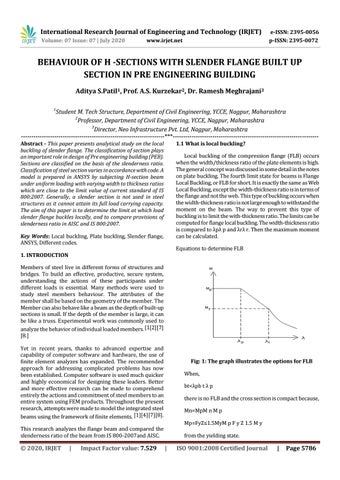
Equations to determine FLB
1. INTRODUCTION Members of steel live in different forms of structures and bridges. To build an effective, productive, secure system, understanding the actions of these participants under different loads is essential. Many methods were used to study steel members behaviour. The attributes of the member shall be based on the geometry of the member. The Member can also behave like a beam as the depth of built-up sections is small. If the depth of the member is large, it can be like a truss. Experimental work was commonly used to analyze the behavior of individual loaded members. [1[2][7] [8.] Yet in recent years, thanks to advanced expertise and capability of computer software and hardware, the use of finite element analyzes has expanded. The recommended approach for addressing complicated problems has now been established. Computer software is used much quicker and highly economical for designing these leaders. Better and more effective research can be made to comprehend entirely the actions and commitment of steel members to an entire system using FEM products. Throughout the present research, attempts were made to model the integrated steel beams using the framework of finite elements. [1][4][7][8].
Fig: 1: The graph illustrates the options for FLB When, bt<λpb t λ p there is no FLB and the cross section is compact because, Mn=MpM n M p Mp=FyZ≤1.5MyM p F y Z 1.5 M y
This research analyzes the flange beam and compared the slenderness ratio of the beam from IS 800-2007and AISC.
© 2020, IRJET
|
Impact Factor value: 7.529
from the yielding state.
|
ISO 9001:2008 Certified Journal
|
Page 5786