International Research Journal of Engineering and Technology (IRJET)
e-ISSN: 2395-0056
Volume: 07 Issue: 06 | June 2020
p-ISSN: 2395-0072
www.irjet.net
AUTOMATED AND WIRELESS CONTROLLED PICK AND PLACE ROBOT MANIPULATOR Mr. A. V. Sutar1, Mr. Salunke Parmeshwar Vitthalrao2, Mr. Kitture Yogesh Prabhakar2, Mr. Raste Akash Uddhav2 1Asst.
Professor, Mechanical Engineering Department, D.K.T.E. Society’s T.E.I., Ichalkaranji 2Students, D.K.T.E. Society’s T.E.I., Ichalkaranji ---------------------------------------------------------------------***---------------------------------------------------------------------
Abstract - In this paper, discussion will be related to Robot Manipulator which has been controlled by Mobile App remotely.
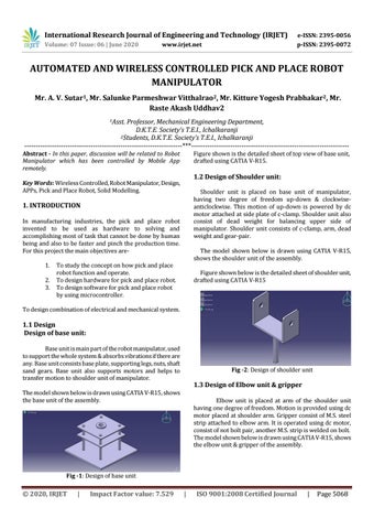
Figure shown is the detailed sheet of top view of base unit, drafted using CATIA V-R15.
1.2 Design of Shoulder unit:
Key Words: Wireless Controlled, Robot Manipulator, Design, APPs, Pick and Place Robot, Solid Modelling.
Shoulder unit is placed on base unit of manipulator, having two degree of freedom up-down & clockwiseanticlockwise. This motion of up-down is powered by dc motor attached at side plate of c-clamp. Shoulder unit also consist of dead weight for balancing upper side of manipulator. Shoulder unit consists of c-clamp, arm, dead weight and gear-pair.
1. INTRODUCTION In manufacturing industries, the pick and place robot invented to be used as hardware to solving and accomplishing most of task that cannot be done by human being and also to be faster and pinch the production time. For this project the main objectives are1. 2. 3.
The model shown below is drawn using CATIA V-R15, shows the shoulder unit of the assembly.
To study the concept on how pick and place robot function and operate. To design hardware for pick and place robot. To design software for pick and place robot by using microcontroller.
Figure shown below is the detailed sheet of shoulder unit, drafted using CATIA V-R15
To design combination of electrical and mechanical system.
1.1 Design Design of base unit: Base unit is main part of the robot manipulator, used to support the whole system & absorbs vibrations if there are any. Base unit consists base plate, supporting legs, nuts, shaft sand gears. Base unit also supports motors and helps to transfer motion to shoulder unit of manipulator.
Fig -2: Design of shoulder unit
1.3 Design of Elbow unit & gripper
The model shown below is drawn using CATIA V-R15, shows the base unit of the assembly.
Elbow unit is placed at arm of the shoulder unit having one degree of freedom. Motion is provided using dc motor placed at shoulder arm. Gripper consist of M.S. steel strip attached to elbow arm. It is operated using dc motor, consist of not bolt pair, another M.S. strip is welded on bolt. The model shown below is drawn using CATIA V-R15, shows the elbow unit & gripper of the assembly.
Fig -1: Design of base unit
© 2020, IRJET
|
Impact Factor value: 7.529
|
ISO 9001:2008 Certified Journal
|
Page 5068