International Research Journal of Engineering and Technology (IRJET)
e-ISSN: 2395-0056
Volume: 07 Issue: 04 | Apr 2020
p-ISSN: 2395-0072
www.irjet.net
Steerable Roger Antenna for 5G Applications Mrs.K.Radha1, M.Uhanjali2, S.Lohitha3, V.Avinash4, SK.Nagur Afil5 1
Assistant Professor, Dept. of Electronics and Communication Engineering, Dhanekula Institute of Engineering and Technology, Andhra Pradesh, India 2,3,4,5 Bachelor of Technology, Dept. of Electronics and Communication Engineering, Dhanekula Institute of Engineering and Technology, Andhra Pradesh, India ---------------------------------------------------------------------***----------------------------------------------------------------------
Abstract - In this study, design of Antenna is modified for
better bandwidth, cost effective and performance in the frequency range of proposed for 5G IOT applications. Antenna having three dielectric resonator antennas in which two of them are parasitic elements and one is driven element operates in two modes TE₍₁‚₁₎ & TE₍₁‚₃₎. The driven element excites the nearby parasitic elements through a principle called mutual coupling. The capacitors which are in the ground layers of parasitic elements are used to get steering which is in the range -320 to +320. The proposed design has gain >7dB and bandwidth of 1.47 GHz with operating frequency of 20.42GHz.
Key Words: Beam steering, Dielectric resonator antenna, higher order mode, Parasitic elements,5G
1. INTRODUCTION Dielectric resonator antenna with parasitic elements of higher order mode was considered in HFSS version 13.In this the antenna design for required beam steering has been designed using HFSS. By switching the termination capacitor on the parasitic element beam steering was successfully achieved. Beam steering may be influenced by two factors. When switching conditions are varied then the change in the beam steering is more relevant to the required results when compared to the change in frequency. So here switching conditions of the capacitor take a major role. As a result, the beam steering of the antenna beam was -320 to 320 at 20.42GHz.
decreased wavelength. In complex phased array design include power distribution in the network, phase shifter and bias component. Whereas the phase shifters are costly and require complex feeding networks which cause more losses at higher frequencies. Hence a new phased arrays are need to be developed for different techniques. In order to overcome this beam steering has been developed without the phase shifters which is known as Electronically Steerable Passive Array Radiator(ESPAR) antenna. It consists of driven and parasitic element. The steerable beam can be adjusted by controlling capacitor values.
1.2 PROPSOED SYSTEM METHODOLOGY We proposed a solution for arising technology 5G applications using a dielectric resonating antenna with parasitic elements. It is a cost effective design which is mainly used for industrial purpose. In this design of antenna it consists of six switches which effect the mutual coupling on the radiation pattern and the reflection coefficient. Here it consists of two DRA’s in which each DRA is associated with three switches.
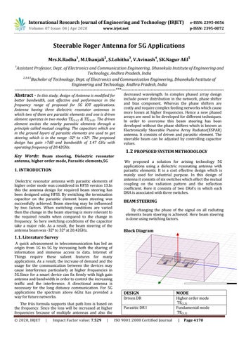
BEAM STEERING By changing the phase of the signal on all radiating elements beam steering is achieved. Here beam steering is done using switching factors.
Block Diagram
1.1. Literature Survey A quick advancement in telecommunication has led an origin from 1G to 5G by increasing both the sharing of information and immense access to data. Internet of Things require these salient features for many applications. As a result, the increase of demand and the usage for the communication between the devices may cause interference particularly at higher frequencies in 5G.Since for a smart device can fix firmly with high gain antenna and bandwidth in order to control the increasing traffic and the interference. A directional antenna is necessary for the long distance communication. For 5G applications the spectrum above 6Ghz has provided a way for future networks. The friis formula supports that path loss is based on the frequency. Since the loss will be increased at higher frequencies because of multiple antennas and also the © 2020, IRJET
|
Impact Factor value: 7.529
|
DESIGN
MODE
Driven DR
Higher order mode TE(1,3) Fundamental mode TE(1,1)
Parasitic DR I ISO 9001:2008 Certified Journal
|
Page 4170