International Research Journal of Engineering and Technology (IRJET)
e-ISSN: 2395-0056
Volume: 07 Issue: 04 | Apr 2020
p-ISSN: 2395-0072
www.irjet.net
Analysis of Skew Bridge using Computational Method Arzoo Patel1, Dhruv patel2 1PG
Scholar, Department of Engineering and Technology, Sakalchand Patel University, Visnagar, Gujarat, India 2 Assistant Professor, Department of Engineering and Technology, Sakalchand Patel University, Visnagar, Gujarat, India ---------------------------------------------------------------------***----------------------------------------------------------------------
Abstract - Bridge is very special type of structures which are characterized by their simplicity in geometry and loading condition. For this study, Dead Load, Impact Load, Vehicular Live Load and Lane Load along with load combination according to IRC & AASHTO are considered. Reinforced concrete T – Beam girder of various skew angle (0°, 15°, 30°, 45°, 60°) and different span (16 m, 18 m, 20 m & 24 m) with 2 lane carriage way is considered. The analysis is done using STAAD Pro Software and grillage method of analysis is used for designing. The skew angle is taken at interval of 15° starting from 0° up to maximum of 60°. The analysis result is present in teams of bending moment, torsion moment, shear force and deflection for T – Beam girder. After end of study conclusion will be made that comparison of skew bridge with normal bridge.
[1]
Significant torsional moment in the deck slab.
[2]
Decrease in longitudinal moment.
[3]
Increase in transverse moment.
[4]
Hogging bending moment near the obtuse corners.
[5]
Concentration of reaction forces and negative moment at the obtuse corner.
[6]
Smaller reaction and possibility of uplift reaction force at the acute corner.
Key Words: IRC: 6, IRC: 112, AASHTO LRFD, STAAD Pro, T – Beam Girder.
1. INTRODUCTION
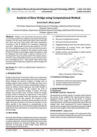
Figure 1 Geometry of Skew bridge
Bridge is special type of structure which covers separation which carry heaviest responsibility of free flow of transport. Many methods are used for analysis of bridge such as grillage analysis, finite analysis of bridge and many more methods. This method of analysis using grillage analogy, is based on stiffness matrix approach, was made flexible to computer programming. In this analysis the deck is represented an equivalent grillage of beams. The finer grillage mesh provide more accurate results for design purpose which is founded by experiments. If the load is smaller than the grillage mesh, the moments and torque cannot be given by this method. The position of the longitudinal members should be always parallel to the free edges while the orientation of transverse members can be either parallel to the supports or perpendicular to the longitudinal beams. Here we used skew bridge with different angle but the force distribution is complicated compared to normal bridge. 1.1 Skew Bridge Now days, Skew Bridge is designed due to space construction in congested urban areas and it gives large variety of solution in railway alignment. Analysis calculation does not provide sufficient accuracy for structural design. The change in direction of load path in skew bridge brings about the following special characteristics.
© 2020, IRJET
|
Impact Factor value: 7.34
|
1.2 Guidelines of Grillage Layout [1] [2] [3]
Idealization of Deck into Equivalent Grillage Location and Direction of Grid Lines Number and Spacing of Grid Lines
2. LOAD ON BRIDGES
2.1 Dead Load AS PER IRC: 6 (2014) – Clause 203 The dead load carried by a girder or member shall consist of the portion of the weight of the superstructure which is supported wholly or in part by the girder or member including its own weight. The following unit weights of materials shall be used to determining loads, unless the unit weights have been determined by actual weighing of representative samples of the materials in question, in which case the actual weights as thus determined shall be used. AS PER AASHTO – Clause 3.5.1 Dead load shall include the weight of all components of the structure and utilities attached thereto, earth cover, wearing surface, future overlays, and planned widening.
ISO 9001:2008 Certified Journal
|
Page 1995