International Research Journal of Engineering and Technology (IRJET)
e-ISSN: 2395-0056
Volume: 07 Issue: 03 | Mar 2020
p-ISSN: 2395-0072
www.irjet.net
DESIGN OF HIGH GAIN DC-DC STEP UP CONVERTER P.DIVYA1, G.ARUNA2, B.GANESH3, V.KISHORE KUMAR4, S.PADMANABHA IYAPPAN5 1,2,3,4Final
year Student, Dept. of Electrical and Electronics Engineering, Professor, Dept. of Electrical and Electronics Engineering, SRM Valliammai Engineering College, Kattankulathur, Tamilnadu, India ---------------------------------------------------------------------***---------------------------------------------------------------------5Assistant
Abstract – An interleaved boost converter with a bi-fold Dickson voltage multiplier suitable for interfacing low-voltage renewable energy sources to high-voltage distribution buses and other applications that require a high-voltage-gain conversion ratio. The proposed converter was constructed from two stages: an interleaved boost stage, which contains two inductors operated by two low-side active switches, and a voltage multiplier cell (VMC) stage, which mainly consists of diodes and capacitors to increase the overall voltage gain. It offers a high voltage gain ratio with low voltage stress on the semiconductor switches as well as the passive component. Moreover, the required inductance that ensures operation in the continuous conduction mode (CCM) is lower than the one in the conventional interleaved boost converter. The distinction of the proposed converter is that the inductors currents are equal, regardless of the number of VMCs. Equal sharing of interleaved boost-stage currents reduces the conduction loss in the active switches as well as the inductors and thus improves the overall efficiency. Key Words: interleaved boost converter, bi-fold Dickson VMC, switched capacitors, coupled inductors I.INTRODUCTION
In recent years, many novel high step-up converters have been developed. Despite these advances, high step-up singleswitch converters are unsuitable to operate at heavy load given a large input current ripple, which increases conduction losses. The conventional interleaved boost converter is an excellent candidate for high-power applications and power factor correction. Unfortunately, the step-up gain is limited, and the voltage stresses on semiconductor components are equal to output voltage. Hence, based on the aforementioned considerations, modifying a conventional interleaved boost converter for high step-up and high-power application is a suitable approach. To integrate switched capacitors into an interleaved boost converter may make voltage gain reduplicate, but no employment of coupled inductors causes the step-up voltage gain to be limited. Oppositely, to integrate only coupled inductors into an interleaved boost converter may make voltage gain higher and adjustable, but no employment of switched capacitors causes the step-up voltage gain to be ordinary. Thus, the synchronous employment of coupled inductors and switched capacitors is a better concept; moreover, high step-up gain, high efficiency, and low voltage stress are achieved even for highpower applications. © 2020, IRJET
|
Impact Factor value: 7.34
|
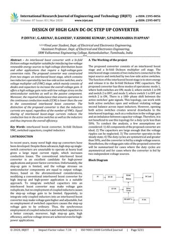
A. The Working of the project The proposed converter consists of an interleaved boost stage and a bi-fold Dickson multiplier cell stage. The interleaved stage consists of two inductors connected to the input source and switched by two low-side active switches. The function of the interleaved boost stage is to store energy and release it to the bi-fold Dickson VMC capacitors. The proposed converter has three modes of operations: mode 1, where both switches are ON; mode 2, where switch 1 is ON and switch 2 is OFF; and mode 3, where switch 1 is OFF and switch 2 is ON.. There is a 180◦ phase shift between the active switches’ gate signals. This topology, can work with both active switches open and without violating voltage second balance across input inductors. However, opening both active switches creates several drawbacks to the interleaved topology, such as a reduction in the voltage gain and an imbalance between capacitor voltage. Therefore, it is not beneficial to use this topology for a duty cycle less than 50%. To conduct the analysis, a few assumptions are considered: 1) All components of the proposed converter are ideal; 2) The capacitors are large enough that the voltage ripples can be neglected; 3) The converter operates in the steady state; 4) The duty cycles are symmetrical and greater than 50%, and the converter is fed by a single voltage source. Nonetheless, the voltage gain ratio of the proposed converter will be summarized for cases where the duty cycles are asymmetrical and for cases where the converter is fed by two independent voltage sources. Block Diagram
ISO 9001:2008 Certified Journal
|
Page 5211