International Research Journal of Engineering and Technology (IRJET)
e-ISSN: 2395-0056
Volume: 07 Issue: 02 | Feb 2020
p-ISSN: 2395-0072
www.irjet.net
Analysis and Implementation of Active Power Filters Neelam Verma1, Garima Vyas2, Geetanjali Meghwal3, Dr Monika Vardia4 1,2,3,4EE
DEPARTMENT GITS,UDAIPUR ----------------------------------------------------------------------***--------------------------------------------------------------------ABSTRACT - Active power filters (APF) are filters, which can perform the job of harmonic elimination. Harmonic, where passive power filters use combinations of resistors (R), inductors (L) and capacitors (C) and does not require an external power source or active components such as transistors. The filter can compensate for harmonic currents, power factor and load unbalance. Together simulation and experimental results are presented, showing that better dynamic and steady-state response can be achieved with this approach. To generate desired APF output voltage by Pulse Width Modulation based on generated reference voltage. Key Words: Active Power Filters (APF), Pulse Width Modulation (PWM), Current Source Inverter (CSI), Voltage Source Inverter (VSI). 1. INTRODUCTION The uses of loads which are not linear in nature and which also vary with time have been continuously increasing in the present time. As a result it causes distortion in current/voltage waveforms and introduces harmonics in it. Ultimately causes poor power factor of power supply. These problems can be eliminated with the help of APF which provides power conditioning. It helps in compensating the reactive power, regulating the voltage and eliminating the harmonics. APF is primarily used for eliminating harmonics on consumer load. The other function is to compensate for voltage imbalance. To distribution system it provides harmonic damping factor.
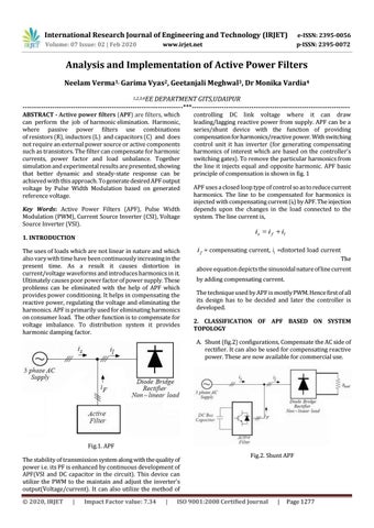
controlling DC link voltage where it can draw leading/lagging reactive power from supply. APF can be a series/shunt device with the function of providing compensation for harmonics/reactive power. With switching control unit it has inverter (for generating compensating harmonics of interest which are based on the controller’s switching gates). To remove the particular harmonics from the line it injects equal and opposite harmonic. APF basic principle of compensation is shown in fig. 1 APF uses a closed loop type of control so as to reduce current harmonics. The line to be compensated for harmonics is injected with compensating current (if) by APF. The injection depends upon the changes in the load connected to the system. The line current is,
is i f il
i f = compensating current, i1 =distorted load current
The
above equation depicts the sinusoidal nature of line current by adding compensating current. The technique used by APF is mostly PWM. Hence first of all its design has to be decided and later the controller is developed. 2. CLASSIFICATION OF APF BASED ON SYSTEM TOPOLOGY A. Shunt (fig.2) configurations, Compensate the AC side of rectifier. It can also be used for compensating reactive power. These are now available for commercial use.
Fig.1. APF The stability of transmission system along with the quality of power i.e. its PF is enhanced by continuous development of APF(VSI and DC capacitor in the circuit). This device can utilize the PWM to the maintain and adjust the inverter’s output(Voltage/current). It can also utilize the method of © 2020, IRJET
|
Impact Factor value: 7.34
|
Fig.2. Shunt APF
ISO 9001:2008 Certified Journal
|
Page 1277