International Research Journal of Engineering and Technology (IRJET)
e-ISSN: 2395-0056
Volume: 07 Issue: 01 | Jan 2020
p-ISSN: 2395-0072
www.irjet.net
A Dual Stage Flyback Converter using VC Method V. Dhinesh1, R. Raja2, S. Karthick3, Dr. S. Saravanan4 1,2,3Assistant
Professor, Muthayammal Engineering College, Rasipuram and Head, Muthayammal Engineering College, Rasipuram ---------------------------------------------------------------------***---------------------------------------------------------------------4Professor
Abstract - This proposed work presents a control strategy for two stage fly-back converter. By using this two stage fly-back converter the instantaneous Voltage Control (VC) scheme is adopted to control the converter. The errors of the reference voltage and the feedback signal of the output voltage are compared. This compared output voltage is compensated with the PI controller with difference control strategy. By using this control strategy the output voltage of the PI controller is compared with the triangular wave to get the driving signals of the synchronous rectifier. This signal are used to shut down the driving signals or keep the driving signals on during the half cycle of the output voltage and by using this control strategy additional freewheeling power can be reduced. The circuit is simulated using MATLAB Simu-link. Key Words: Fly back converter, voltage control method, PI controller. 1. INTRODUCTION Fly-back converter is used in both AC/DC and DC/DC conversion with a galvanic isolation between the input and output. In many ways, a dc-dc converter is the dc equivalent of a transformer. More precisely, the fly-back converter is just like a buck boost converter with the inductor split to form a transformer, so that the voltage ratios are multiplied with an additional advantage of isolation.
When MOSFET is switched on, current flows from the source to the primary winding N1 and energy is stored in the transformer’s magnetic field. When the switch is turned off, the transformer tries to maintain the current flow through N1 by suddenly reversing the voltage across it generating a fly-back pulse. When the switch is chosen to have a very high breakdown voltage, through, so current simply cannot be maintained to the primary circuit .but because of the transformer action an even higher fly-back pulse is induced in the secondary winding N2 and here diode |
Impact Factor value: 7.34
The fly-back converter again has two distinct phases in its switching cycle. During the first phase switch conducts and energy is store in the transformer core through the primary winding N1. Then in the second phase when switch is turned off, the stored energy is transformed into the load and C1 through the secondary winding. DC to DC converters are important in portable electronic devices such as cellular phones and laptop computers, which are supplied with power from batteries primarily. Such electronic devices often contain several subcircuits, each with its own voltage level requirement different from that supplied by the battery or an external supply (sometimes higher or lower than the supply voltage). Additionally, the battery voltage declines as its stored power is drained. Switched DC to DC converters offer a method to increase voltage from a partially lowered battery voltage thereby saving space instead of using multiple batteries to accomplish the same thing. The commonly used fly-back converter requires a single controllable switch like, MOSFET and the usual switching frequency is in the range of 50 kHz. A two-switch topology exists that offers better energy efficiency and less voltage stress across the switches. Input to the circuit may be unregulated dc voltage derived from the utility ac supply after rectification and some filtering. The ripple in dc voltage waveform is generally of low frequency and the overall ripple voltage waveform repeats at twice the ac mains frequency. Since the fly-back converter circuit is operated at much higher frequency the input voltage, in spite of being unregulated, may be considered to have a constant magnitude during any high frequency cycle. A fast switching device, like a MOSFET, is used with fast dynamic control over switch duty ratio (ratio of ON time to switching time-period) to maintain the desired output voltage.
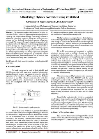
Fig: 1.1 Single stage fly-back converter
Š 2020, IRJET
D1 is able to conduct during the pulse, delivering current to the load and recharging filter capacitor C1.
|
A. Mode-1 of Circuit Operation. Fig1.2 shows the current carrying part of the circuit and the circuit that is functionally equivalent to the fly-back circuit during mode-1. In the equivalent circuit
ISO 9001:2008 Certified Journal
|
Page 1057