International Research Journal of Engineering and Technology (IRJET) Volume: 06 Issue: 05 | May 2019 www.irjet.net
e-ISSN: 2395-0056 p-ISSN: 2395-0072
“STATIC STRUCTURAL AND MODAL ANALYSIS OF SECONDARY AIR FLOW SYSTEM” Akash Shindolkar1, Sachin Patil1, Yogesh Hangirgekar1, Nikhil Patil1, Revanasiddappa Havaragi2 1 Student 2 Assistance
Dept. of Mechanical Engineering, MMEC, Belagavi, Karnatak, INDIA
Prof. Dept. of Mechanical Engineering, MMEC, Belagavi, Karnatak, INDIA
---------------------------------------------------------------------------------------------------------------------------------------------Abstract - Secondary air flow system play a significant role in turbine engine to accomplish reliable operation of the individual modules as well as the whole engine. Main functions of secondary air flow system are to provide cooling flow to engine components, to seal bearing chamber and to control bearing axial loads. Being a functional discipline, secondary air flow system owns the air flow that is essentially not the primary flowpath. In this study, solid modelling of Secondary air flow system having trapezoidal cross-section referring to one of its existing design is done using CATIA V5. Further, analyses are carried out in ANSYS Workbench. Further, Modal analysis is carried out to determine the vibration characteristics such as natural frequencies and mode shapes. The combination of frequency and amplitude is found to be efficient method for reducing or controlling applied forces which generate stress.
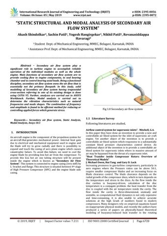
Fig 1.0 Secondary air flow system 1.1 Literature Survey
Keywords— Secondary air flow system, Static Analysis, Modal Analysis, Ansys 18.1
Following literatures are studied, Airflow control system for supersonic inlets”. Mitchell, G.A. In this paper they have done an invention to provide a new and controllable air bleed system for the inlet of supersonic air craft engine. Yet another object of the invention is to provide a controllable air bleed system which responsive to a substantially constant bleed pressure characteristics control device. An additional object of the invention is to provide a controllable air bleed system for supersonic inlets where in massive amount of air may be bypassed from the throat of a supersonic inlet. “Heat Transfer inside Compressor Rotors: Overview of Theoretical Models” J. Michael Owen, Hui Tang and Gary D. Lock Increasing pressures in gas-turbine compressors, particularly in aero engines where the Pressure ratios can be above 50:1, require smaller compressor blades and an increasing focus on Blade clearance control. The blade clearance depends on the radial growth of the compressor discs, which in turn depends on the temperature and stress in the discs. As the flow inside the disc cavities is buoyancy-driven, calculation of the disc temperature is a conjugate problem: the heat transfer from the disc is coupled with the air temperature inside the cavity. The flow inside the cavity is three-dimensional, unsteady and unstable, so computational fluid dynamics is not only expensive and time-consuming, it is also unable to achieve accurate solutions at the high Grash of numbers found in modern compressors. Many designers rely on empirical equations based on inappropriate physical models, and recently the authors have produced a series of papers on physically-based theoretical modeling of buoyancy-induced heat transfer in the rotating
1. INTRODUCTION An aircraft engine is the component of the propulsion system for an aircraft that generates mechanical power. Internal heat gain due to electrical and mechanical equipment used in engine and the blade will try to grow radially and there is possibility to expand and touch the casing of aero plane engine which causes catastrophic failure. To avoid this failure, we need to cool the engine blade by providing less hot air from the compressor. To provide this less hot air one tubing structure will be present inside the engine which is known as “Secondary Air Flow System”. This system is connected to engine casing (very stiff) by L- bracket and flange. This structure is situated between 4 th stage of High Pressure Compressor (HPC) and the engine blade side casing.
© 2019, IRJET
|
Impact Factor value: 7.211
|
ISO 9001:2008 Certified Journal
|
Page 6720