International Research Journal of Engineering and Technology (IRJET)
e-ISSN: 2395-0056
Volume: 06 Issue: 05 | May 2019
p-ISSN: 2395-0072
www.irjet.net
Analysis of LVRT Capability of Grid Connected Solar Photovoltaic System Jenitha. J1, R. Rajeswari2 1M.E
II Year, Department of EEE, Government College of Technology, Coimbatore, India. Professor, Department of EEE, Government College of Technology ,Coimbatore, India. ---------------------------------------------------------------------***---------------------------------------------------------------------2Associate
Abstract - The penetration of Distributed Generation (DG)
of the system and the voltage of near and far end buses of the system is analyzed during fault condition.
sources such as Photovoltaic (PV) power plants are becoming more prominent in the electric grid due to the incremental demands for electrical energy. However, fault condition in the grid, not only can cause the disconnection of grid connected PV systems but also disturb the stability of the main grid and can cause detrimental influence on the availability and reliability of the whole system. Due to this, many countries have established grid code requirements for grid connected PV system that should be met. Hence a control strategy has been proposed in this paper in accordance with the grid code requirements, in order to withstand the low voltage condition in the grid. Therefore the widespread loss of generation can be avoided to a great extent. The functionality of proposed control strategy is verified using Matlab/Simulink environment under unbalanced fault in the standard IEEE power system.
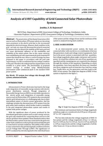
2. IEEE 14 BUS SYSTEM In an interconnected power system, the buses are connected either with one device or a combination of devices like generators, loads and voltage control equipments. Each bus in the power system is associated with four quantities, bus voltage magnitude, phase angle, real power and reactive power. In a load flow solution two out of four quantities are specified and the remaining two are required to be obtained through the solution of the equations. Depending on which the quantities have been specified, the buses are classified into three categories such as Generator bus, load bus, swing bus. Totally there are five generators and nine loads in the IEEE 14 bus system. The single line diagram of IEEE 14 bus system is depicted in the figure 1.
Key Words: PV system, low voltage ride through, IEEE system, unbalanced faults.
1. INTRODUCTION Advancement in Power electronics has lead to the large scale integration of renewable energy systems with electric power distribution network. Though integration of Renewable Energy Sources (RES) is an inevitable operation in the electric grids, such integration of renewable energy sources such as Photovoltaic (PV) system to the conventional electric grid infrastructure is a challenging task, due to their intermittent nature of electric power generation. And the challenge includes the disconnection of PV system from the grid under fault condition, which further leads to instability in the grid integrated photovoltaic system and results in system wide power outages.
Fig -1: Single line diagram of IEEE 14 bus system The minimum and maximum limits of voltage magnitude and phase angle are considered to be 0.95 pu to 1.05 pu and 45° to +45° respectively.
With the significant share of power produced by the distributed generation system such as solar energy sources, the grid code standards for connecting these sources to the electric grid have been updated. These standards enforce that the Photovoltaic system must stay connected to the grid even under fault conditions in short periods and must help the grid to come back to normal conditions. This ability of the system to stay connected to the grid during fault condition is known as Low Voltage Ride Through (LVRT) .The significance of LVRT is analyzed by introducing fault in the individual buses
Š 2019, IRJET
|
Impact Factor value: 7.211
The bus data indicates the voltage magnitude of IEEE 14 bus system and the voltage magnitude of bus 1 is 1.06 pu, bus 2 is 1.045 pu, bus 3 is 1.01 pu , bus 6 is 1.07 pu and bus 8 is 1.09 pu respectively and the voltage magnitude of all the other buses are 1.0 pu as shown in table1.
|
ISO 9001:2008 Certified Journal
|
Page 5938