International Research Journal of Engineering and Technology (IRJET)
e-ISSN: 2395-0056
Volume: 06 Issue: 05 | May 2019
p-ISSN: 2395-0072
www.irjet.net
FEM Analysis of Universal Joint of Bharath Benz DE210BS4 Ananthu S Kumar1, Rahul P John2 1Mtech
Student, Sri Vellappally Natesan College of Engineering, Mavelikara, Kerala Professor, Sri Vellappally Natesan College of Engineering, Mavelikara, Kerala ----------------------------------------------------------------------***--------------------------------------------------------------------1.1 Cross-Type Joint Abstract - The power generated in the engine as the result 2Assistant
of combustion of fuel is transformed to wheels through the transmission system in the vehicle. This system mainly consist of gear box, propeller shafts, universal joints and differential gears. The drive shaft imparts torque from the engine. The failures that caused to the driveshaft is mainly due to vibtational stress, fatigue, bending stress or even the misalignment of the driveshaft. All these defects are mainly due to the overloading or even repeated overtime use. Our project mainly aims at testing the universal joint at different working angles and different materials so that the time to time failure of the universal joint can be reduced to some extent.
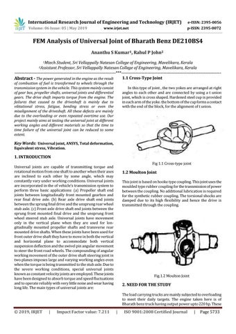
In this type of joint , the two yokes are arranged at right angles to each other and are connected by using a t union joint, which is cross shaped. Hardened steel cup is provided in each arm of the yoke. the bottom of the cup forms a contact with the end of the block, for the alignment of t union.
Key Words: Universal joint, ANSYS, Total deformation, Equivalent stress, Vibration.
1. INTRODUCTION Fig 1.1 Cross-type joint
Universal joints are capable of transmitting torque and rotational motion from one shaft to another when their axes are inclined to each other by some angle, which may constantly vary under working conditions. Universal joints are incorporated in the of vehicle’s transmission system to perform three basic applications: (a) Propeller shaft end joints between longitudinally front mounted gearbox and rear final drive axle. (b) Rear axle drive shaft end joints between the sprung final drive and the unsprung rear wheel stub axle. (c) Front axle drive shaft end joints between the sprung front mounted final drive and the unsprung front wheel steered stub axle. Universal joints have movement only in the vertical plane when they are used for longitudinally mounted propeller shafts and transverse rear mounted drive shafts. When these joints have been used for front outer drive shaft they have to move in both the vertical and horizontal plane to accommodate both vertical suspension deflection and the swivel pin angular movement to steer the front road wheels. The compounding of angular working movement of the outer drive shaft steering joint in two planes imposes large and varying working angles even when the torque is being transmitted to the stub axle. Due to the severe working conditions, special universal joints known as constant velocity joints are employed. These joints have been designed to absorb torque and speed fluctuations and to operate reliably with very little noise and wear having long life. The main types of universal joints are:
1.2 Moulton Joint This joint is based on hooke type coupling. This joint uses the moulded type rubber coupling for the transmission of power between the coupling. No additional lubrication is required for the synthetic rubber coupling. The torsional shocks are damped due to its high flexibility and hence the drive is transmitted through the coupling.
Fig.1.2 Moulton Joint
2. NEED FOR THE STUDY The load carrying trucks are mainly subjected to overloading to meet their daily targets. The engine taken here is of Bharath benz truck having output power upto 220 hp. These
Š 2019, IRJET
|
Impact Factor value: 7.211
|
ISO 9001:2008 Certified Journal
|
Page 5733