International Research Journal of Engineering and Technology (IRJET)
e-ISSN: 2395-0056
Volume: 06 Issue: 05 | May 2019
p-ISSN: 2395-0072
www.irjet.net
IMPLEMENTATION OF MODIFIED H-BRIDGE MULTILEVEL INVERTER TOPOLOGY FOR SOLAR PHOTOVOLTAIC SYSTEM ELAVARASI S1, Dr. SUJATHA BALARAMAN2 1ME-Power
Electronics and Drives, Department of Electrical and Electronics Engineering, Government College of Technology, Coimbatore, Tamil nadu, India 2Associate Professor, Department of Electrical and Electronics Engineering, Government College of Technology, Coimbatore, Tamil nadu, India ----------------------------------------------------------------------***--------------------------------------------------------------------Abstract - In this project, a new configuration of Multilevel Inverter (MLI) topology based on modified H-bridge seven level inverter is proposed, which can produce more voltage level with reduced number of switches when compared with cascaded H-bridge topology. In proposed MLI topology, only eight switches are required to generate seven level output, whereas twelve switches are required for conventional cascade H-bridge topology. Moreover, to resolve problems related to dc source fluctuations with Solar Photovoltaic, the Sinusoidal Pulse Width Modulation (SPWM) technique is developed. The switching losses, voltage stress on power devices and cost are reduced due to less number of switches. Further, Total Harmonic Distortion (THD) of load current less than 2% is achieved with small size low pass filter. Simulation results has been done in MATLAB and to validate the feasibility and performance of seven level Multilevel Inverter hardware setup has been developed. The PIC Microcontroller is used to produce gate signals based on SPWM technique for the gates of the MOSFET switches. The results are verified experimentally with seven level Multilevel Inverter circuit for 10 W Solar Panel with resistive load.
clamped multilevel inverter, flying capacitor multilevel inverter, cascaded H-bridge multilevel inverter, and modified H-bridge multilevel inverter. The proposed circuit is based on a resonant switched capacitor converter (RSCC), and voltage balancing of input capacitor technique. The main purpose of multilevel inverter topology for high power industrial applications and switching losses, voltage stress on power devices and costs are reduced due to less number of switches.
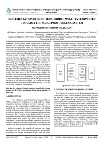
Fig- 1: Seven level multilevel inverter
Key Words: Low switching frequency, Modified H-bridge converter, SPWM technique and Single phase seven level inverter.
2. TOPOLOGY OF MODIFIED H-BRIDGE INVERTER H-bridge is an electronic circuit that enables a voltage to be applied across a load in either direction. These circuits are used for robotics and other applications to allow DC motors to run forwards and backwards. Most DC-to-AC converters (power inverters), most AC-to-AC converters, the DC-to-DC push–pull converter, most motor controllers, and many other kinds of power electronics use H bridges. In particular, a bipolar stepper motor is almost invariably driven by a motor controller containing Two H Bridges. Three-phase configuration can be easily implemented by three single-phase structures. Soft switching techniques can be used to reduce switching losses and device stresses. The advantages are; (1) switching at (or nearly) the fundamental frequency, drastically reduces switching losses. (2) elimination of the transformer in providing required voltage levels. (3) easier packaging due to the simplicity of its structure and its low component count.
1. INTRODUCTION The multilevel inverter has been introduced since 1975 as alternative in high power and medium voltage situations. Various multilevel inverter topologies were proposed in the past decade, which have been extensively studied for renewable energy integration systems.The multilevel inverter generated the sinusoidal output voltage waveform, where power switches operated at low switching frequency. Fig 1 shows seven level multilevel inverter powered with solar photovoltaic. Which operates on seven voltage levels and inverts the direct current (DC) to alternating current (AC) with lower switching losses and reduced harmonic distortion. The AC load is connected to the inverter and inverter producing a sinusoidal output voltage. Various topologies for multilevel inverter have been proposed over the years, aiming to construct a sinusoidal waveform for several DC-voltage levels, such as diode
Š 2019, IRJET
|
Impact Factor value: 7.211
|
ISO 9001:2008 Certified Journal
|
Page 5585