International Research Journal of Engineering and Technology (IRJET)
e-ISSN: 2395-0056
Volume: 06 Issue: 05 | May 2019
p-ISSN: 2395-0072
www.irjet.net
Impact Resistances of Hybrid Steel Truss Beams Rashida p k1, kiran jacob2 1Mtech
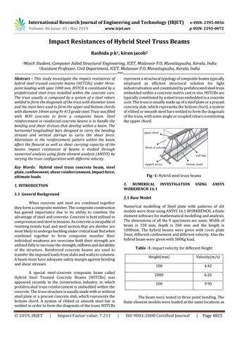
Student, Computer Aided Structural Engineering, ICET, Mulavoor P.O, Muvattupuzha, Kerala, India 2Assistant Professor, Civil Department, ICET, Mulavoor P.O, Muvattupuzha, Kerala, India ----------------------------------------------------------------------***--------------------------------------------------------------------Abstract - This study investigate the impact resistances of hybrid steel trussed concrete beams (HSTCBs) under threepoint loading with span 1000 mm. HSTCB is constituted by a prefabricated steel truss installed within the concrete core. The truss usually is composed by a system of a steel rebars welded to form the diagonals of the truss with diameter 6mm and the main bars used to form the upper and bottom chords with diameter 10mm using Fe 415 grade steel. Truss was filled with M30 concrete to form a composite beam. Steel reinforcement in reinforced concrete beams is to handle the bending and shear stresses that develop within a beam. The horizontal longitudinal bars designed to carry the bending stresses and vertical stirrups to carry the shear force. Alterations in the reinforcement pattern within the beam affect the flexural as well as shear carrying capacity of the beams. impact resistances of beams is studied through numerical analysis using finite element analysis (ANSYS) by varying the truss configuration with different velocity.
represent a structural typology of composite beams typically employed as efficient structural solution for light industrialization and constituted by prefabricated steel truss embedded within a concrete matrix cast in situ. HSTCBs are typically constituted by a steel truss embedded in a concrete core. The truss is usually made up of a steel plate or a precast concrete slab, which represents the bottom chord, a system of ribbed or smooth steel bars welded to form the diagonals of the truss, with some single or coupled rebars constituting the upper chord.
Key Words: Hybrid steel truss concrete beam, steel plate, confinement, shear reinforcenment, impact force, ultimate loads
Fig -1: Hybrid steel truss beams 2. NUMERICAL INVESTIGATION WORKBENCH 16.1
1. INTRODUCTION 1.1 General Background
Numerical modelling of Steel plate with patterns of slit models were done using ANSYS 16.1 WORKBENCH, a finite element software for mathematical modelling and analysis. The dimensions of all the 9 specimens are same. Width of beam is 150 mm, depth is 260 mm and the length is 1000mm. The hybrid beams were given with cover plate 3mm, different confinement and different velocity. Also the hybrid beam were given with 500Kg load. Table -1: impact velocity for different Height
A special steel-concrete composite beam called Hybrid Steel Trussed Concrete Beams (HSTCBs) was appeared recently in the construction industry, in which prefabricated truss reinforcement is embedded within the concrete. The truss structure is usually made with or without steel plate or a precast concrete slab, which represents the bottom chord. A system of ribbed or smooth steel bar is welded in order to form the diagonals of the truss. HSTCBs
|
Impact Factor value: 7.211
ANSYS
2.1 Base Model
When concrete and steel are combined together they form a composite member. The composite construction has gained importance due to its ability to combine the advantage of steel and concrete. Concrete is best utilized in compression and steel in tension. As concrete is incapable of resisting tensile load and steel section that are slender are most likely to undergo buckling under critical load. But when combined together to form composite member their individual weakness are overcome both their strength are utilized fully to increase the strength, stiffness and durability of the structure. Reinforced concrete beams are used to transfer the imposed loads from slabs and walls to columns. A beam must have adequate safety margin against bending and shear stresses
Š 2019, IRJET
USING
Height(mm)
Velocity(m/s)
100
4.42
2000
6.26
500
9.90
The beam were tested in three point bending. The finite element models were loaded at the same locations as
|
ISO 9001:2008 Certified Journal
|
Page 4825