International Research Journal of Engineering and Technology (IRJET)
e-ISSN: 2395-0056
Volume: 06 Issue: 05 | May 2019
p-ISSN: 2395-0072
www.irjet.net
Under normal operation the traffic lights are controlled based on the conventional timer system. Consider an ambulance approaching junction J1 from north and it wants to go straight to J2. Once the ambulance pass RFID reader R1, R1 sends the ambulance ID and the lat/lng value to the cloud. The server logic then checks for the nearest lat/lng value in the route information table (stored earlier) and publishes the corresponding maneuver data to the topic which the signal controller at J1 is subscribed. J1 on receiving the message (e.g. ‘straight’) overrides the normal operation and turns the corresponding traffic light green, clearing the track for the ambulance to smoothly pass through. Ambulance on passing R2 indicates an exit from junction J1 and the normal operation is restored.
2. Signal Light Controller Signal Light Controller is an MQTT device. MQTT is a lightweight, publish – subscribe system where we can publish and receive message like a client. It is a perfect solution for IoT applications. Signal light controllers are placed at each traffic light junction. It basically controls the functioning of each traffic signal light. Under normal condition, the traffic lights are controlled based on the conventional timer system. Each device is subscribed to a particular topic. The server logic finds out the corresponding maneuver field data and publishes that data onto the respective topic the signal light controller is subscribed.
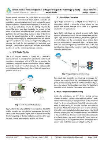
1. RFID Reader Module The RFID Reader module is based on a NodeMCU microcontroller. It consists of an active RFID reader. Each Ambulance is equipped with a RFID tag. As soon as the ambulance passes the RFID reader module, it sends a REST post to the cloud server, which contains the ambulance ID and the latitude and longitude value of the traffic signal light junction ahead of it. Fig -7: Signal Light Controller Setup. The signal light controller on receiving a message (for example “turn right”) turns the corresponding traffic light green, thereby clearing the track for the ambulance. Fig. 7, shows the setup of the Signal light controller. The Signal light controller is also based on a NodeMCU microcontroller.
3.3 Real Time Patient Monitoring Inside the ambulance, an IoT device having various biomedical sensors, can be connected to the patient’s body for real time monitoring of vital parameters by the doctor via cloud. The device is based on the NodeMCU microcontroller board. A user friendly IoT platform ‘Adafruit IO’ is used in this project. Adafruit IO libraries are used to send data from NodeMCU to the cloud platform. Biological sensors like blood pressure, temperature and pulse rate sensors are connected to the patient’s body. The microcontroller collects the data from these sensors and sends it to the IoT cloud platform. The interfacing of blood pressure sensor and temperature sensor with NodeMCU is shown in Fig. 8 and Fig. 9.
Fig -6: RFID Reader Module Setup. Fig. 6, shows the setup of RFID Reader module. The RFID reader modules are placed at an approximate distance of about 150m ahead of each signal point in order to avoid any kind of tailgating, so that the ambulance can smoothly pass through a signal point junction without any delay.
© 2019, IRJET
|
Impact Factor value: 7.211
|
ISO 9001:2008 Certified Journal
|
Page 2045