International Research Journal of Engineering and Technology (IRJET)
e-ISSN: 2395-0056
Volume: 06 Issue: 03 | Mar 2019
p-ISSN: 2395-0072
www.irjet.net
Analysis of Rivet Joint for Application of Substation Yogesh Bagale1, Swapnil Nagarkar2, Lokesh Attarde 3, Kunal Bhadane4 APankaj
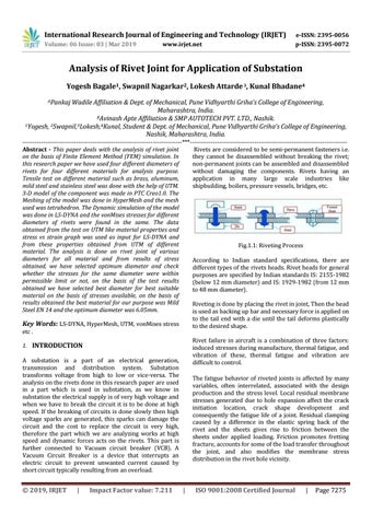
Wadile Affiliation & Dept. of Mechanical, Pune Vidhyarthi Griha’s College of Engineering, Maharashtra, India. BAvinash Apte Affiliation & SMP AUTOTECH PVT. LTD., Nashik. 1Yogesh, 2Swapnil,3Lokesh,4Kunal, Student & Dept. of Mechanical, Pune Vidhyarthi Griha’s College of Engineering, Nashik, Maharashtra, India. -----------------------------------------------------------------------------***---------------------------------------------------------------------------Abstract - This paper deals with the analysis of rivet joint Rivets are considered to be semi-permanent fasteners i.e. on the basis of Finite Element Method (FEM) simulation. In they cannot be disassembled without breaking the rivet; this research paper we have used four different diameters of non-permanent joints can be assembled and disassembled rivets for four different materials for analysis purpose. without damaging the components. Rivets having an Tensile test on different material such as brass, aluminum, application in many large scale industries like mild steel and stainless steel was done with the help of UTM. shipbuilding, boilers, pressure vessels, bridges, etc. 3-D model of the component was made in PTC Creo1.0. The Meshing of the model was done in HyperMesh and the mesh used was tetrahedron. The Dynamic simulation of the model was done in LS-DYNA and the vonMises stresses for different diameters of rivets were found in the same. The data obtained from the test on UTM like material properties and stress vs strain graph was used as input for LS-DYNA and from these properties obtained from UTM of different Fig.1.1: Riveting Process material. The analysis is done on rivet joint of various diameters for all material and from results of stress According to Indian standard specifications, there are obtained, we have selected optimum diameter and check different types of the rivets heads. Rivet heads for general whether the stresses for the same diameter were within purposes are specified by Indian standards IS: 2155-1982 permissible limit or not, on the basis of the test results (below 12 mm diameter) and IS: 1929-1982 (from 12 mm obtained we have selected best diameter for best suitable to 48 mm diameter). material on the basis of stresses available, on the basis of results obtained the best material for our purpose was Mild Riveting is done by placing the rivet in joint, Then the head Steel EN 14 and the optimum diameter was 6.05mm. is used as backing up bar and necessary force is applied on to the tail end with a die until the tail deforms plastically Key Words: LS-DYNA, HyperMesh, UTM, vonMises stress to the desired shape. etc . Rivet failure in aircraft is a combination of three factors: 1. INTRODUCTION induced stresses during manufacture, thermal fatigue, and vibration of these, thermal fatigue and vibration are A substation is a part of an electrical generation, difficult to control. transmission and distribution system. Substation transforms voltage from high to low or vice-versa. The The fatigue behavior of riveted joints is affected by many analysis on the rivets done in this research paper are used variables, often interrelated, associated with the design in a part which is used in substation, as we know in production and the stress level. Local residual membrane substation the electrical supply is of very high voltage and stresses generated due to hole expansion affect the crack when we have to break the circuit it is to be done at high initiation location, crack shape development and speed. If the breaking of circuits is done slowly then high consequently the fatigue life of a joint. Residual clamping voltage sparks are generated, this sparks can damage the caused by a difference in the elastic spring back of the circuit and the cost to replace the circuit is very high, rivet and the sheets gives rise to friction between the therefore the part which we are analyzing works at high sheets under applied loading. Friction promotes fretting speed and dynamic forces acts on the rivets. This part is fracture, accounts for some of the load transfer throughout further connected to Vacuum circuit breaker (VCB). A the joint, and also modifies the membrane stress Vacuum Circuit Breaker is a device that interrupts an distribution in the rivet hole vicinity. electric circuit to prevent unwanted current caused by short circuit typically resulting from an overload.
© 2019, IRJET
|
Impact Factor value: 7.211
|
ISO 9001:2008 Certified Journal
|
Page 7275