International Research Journal of Engineering and Technology (IRJET)
e-ISSN: 2395-0056
Volume: 06 Issue: 04 | Apr 2019
p-ISSN: 2395-0072
www.irjet.net
AN ACTIVE PARTIAL SWITCH POWER FACTOR COORECTION USING HIGH STEP UP INTERLEAVED BOOST CONVERTER G.KAVINRAJ 1, T.RAJKUMAR2 1P.G
Scholar, Department of EEE, The Kavery Engineering College, Salem Professor, Department of EEE, The Kavery Engineering College, Salem ---------------------------------------------------------------------***---------------------------------------------------------------------2Assistant
Abstract - A single-phase, Interleaved AC/DC power factor
topologies have been developed for the PFC applications. The conventional PFC converter is a full-bridge rectifier followed by a interleaved boost converter. The converter is widely used, because of its simplicity. However, due to boosting behavior of the converter, the output voltage is always greater than the input voltage. In many applications, such as low-voltage and low-power supplies, it is desired to have the output voltage.
correction (PFC) rectifier with high gain output voltage is proposed in this paper. For low output voltage product applications, the rectifier is designed to convert high input voltage to low output voltage. Due to no bridge-diodes required and thus decreased input conduction losses, the proposed rectifier efficiency can be improved. The proposed rectifier operates in discontinuous conduction mode and the current-loop circuit is hence not needed. Also, only a single switch is used in the rectifier to simplify the control circuit design. A simple translation method to have the positive output voltage in the interleaved converter is presented in the rectifier to reduce the component counts and the cost as well. The operational principles, steady-state analysis, and design procedure of the proposed rectifier are addressed in detail in this project. Many electronic appliances powered up from the utility, utilize the classical method of ac-dc rectification which involves a diode bridge rectifier followed by a large electrolytic capacitor. The uncontrolled charging and discharging of this capacitor instigates harmonic rich current being drawn from the utility which goes against the international power quality standard limits. Modern ac-dc converters incorporate power factor correction (PFC).
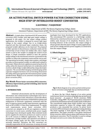
1.1 Block Diagram
Key Words: Power factor correction (PFC) converter, efficiency improvement, partial switching, inter leaved boost converter.
Fig-1: Block diagram of an active partial switch power factor correction using high step up interleaved boost converter
1. INTRODUCTION Industrial advancements and the development of information and communication technologies have led to increases in nonlinear loads, which have caused side effects such as increasing the harmonics of distribution systems and malfunction of electronic equipment connected with the grid. To improve power quality, input harmonic regulations such as IEC-61000-3-2 have been implemented. To satisfy such requirements, power factor correction (PFC) converters are adopted as AC-DC pre-regulators of power conversion In recent years, switched-mode power supply technologies have developed rapidly. Most switched-mode power supplies for electronic products are used to convert AC to DC sources in different applications. The use of a transformer, a bridge rectifier, and capacitors can achieve a DC-output voltage easily, but the input current may be seriously distorted. Therefore, the PFC converters are critically required for AC-DC conversion. A variety of circuit
Š 2019, IRJET
|
Impact Factor value: 7.211
In above the fig-1 Block diagram of an active partial switch power factor correction using high step up interleaved boost converter , It consist of DC-DC converter, PWM, Controller, voltage MMT. The Proposed system connected to an electricity distribution network usually needs rectification. The conventional single phase diode rectifier uses a large electrolytic capacitor to reduce DC voltage ripple, which produces a non sinusoidal line current. So power factor correction (PFC) techniques are gaining increasing attention. The boost topology is most popular than others in PFC applications. This paper presents a two-phase interleaved boost converter which ensures phase shift between the two interleaved converters. The PI controller is used to reshape the input current so as to reduce the harmonics.
|
ISO 9001:2008 Certified Journal
|
Page 2793