International Research Journal of Engineering and Technology (IRJET)
e-ISSN: 2395-0056
Volume: 06 Issue: 02 | Feb 2019
p-ISSN: 2395-0072
www.irjet.net
Generalized UPQC System with an Improved Control Method under Distorted and Unbalanced Load Conditions Shraddha Bele1, Pratik Ghutke2 1PG
Student, Department of Electrical Engineering, TGPCET, Nagpur, Maharashtra, India Professor, Department of Electrical Engineering, TGPCET, Nagpur, Maharashtra, India ---------------------------------------------------------------------***---------------------------------------------------------------------2Asst.
Abstract - Whenever we consider unified power quality conditioner [UPQC], we ae to consider two things (1) voltage sag, (2) voltage swell on the power network. The power remains an important factor while considering its application. The important factor that provides poor power factor are harmonic current, supply voltage variations etc. here in our project we will be using UPQC which will diminish voltage and current related power quality problems. It also improves the harmonics ad correct the power factor of the load. The UPQC is designed by using MATLAB/SIMULINK based simulation for the working of the UPQC.
swell is the brief increase in the RMS voltage of 10-70% of the normal line voltage with a duration off 0.5 to 1 min. An interruption in the transmission line is defined as the normal reduction in the line voltage which occurs for 10% of the nominal value. Voltage fluctuations are normally very small (less than 5%) but distort the power factor. The harmonic distortion originates in the non-linear characteristics of the devices connected to the load side of the power system. Thus higher quality power factor remains an issue for increasing demand of the consumers. 3. Basic design of UPQC
Key Words: UPQC, power factor, voltage sag and voltage swell.
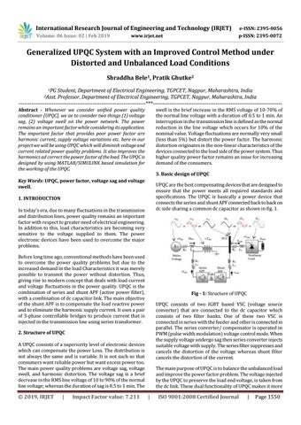
UPQC are the best compensating devices that are designed to ensure that the power meets all required standards and specifications. The UPQC is basically a power device that connects the series and shunt APF connected back to back on dc side sharing a common dc capacitor as shown in fig. 1.
1. INTRODUCTION In today’s era, due to many fluctuations in the transmission and distribution lines, power quality remains an important factor with respect to greater need of electrical engineering. In addition to this, load characteristics are becoming very sensitive to the voltage supplied to them. The power electronic devices have been used to overcome the major problems. Before long time ago, conventional methods have been used to overcome the power quality problems but due to the increased demand in the load Characteristics it was merely possible to transmit the power without distortion. Thus, giving rise to modern concept that deals with load current and voltage fluctuations in the power quality. UPQC is the combination of series and shunt APF (active power filter), with a combination of dc capacitor link. The main objective of the shunt APF is to compensate the load reactive power and to eliminate the harmonic supply current. It uses a pair of 3-phase controllable bridges to produce current that is injected in the transmission line using series transformer.
Fig - 1: Structure of UPQC UPQC consists of two IGBT based VSC (voltage source converter) that are connected to the dc capacitor which consists of two filter banks. One of these two VSC is connected in series with the feeder and other is connected in parallel. The series converter/ compensator is operated in PWM (pulse width modulation) voltage control mode. When the supply voltage undergo sag then series converter injects suitable voltage with supply. The series filter suppresses and cancels the distortion of the voltage whereas shunt filter cancels the distortion of the current.
2. Structure of UPQC A UPQC consists of a superiority level of electronic devices which can compensate the power Loss. The distribution is not always the same and is variable. It is not such so that consumers want reliable power but want excess power too. The main power quality problems are voltage sag, voltage swell, and harmonic distortion. The voltage sag is a brief decrease in the RMS line voltage of 10 to 90% of the normal line voltage; whereas the duration of sag is 0.5 to 1 min. The
Š 2019, IRJET
|
Impact Factor value: 7.211
The main purpose of UPQC is to balance the unbalanced load and improve the power factor problem. The voltage injected by the UPQC to preserve the load end voltage, is taken from the dc link. These dual functionality of UPQC makes it more
|
ISO 9001:2008 Certified Journal
|
Page 1550