International Research Journal of Engineering and Technology (IRJET)
e-ISSN: 2395-0056
Volume: 06 Issue: 02 | Feb 2019
p-ISSN: 2395-0072
www.irjet.net
Performance and Evaluation of Voltage Source Inverter Feed Induction Motor Drive Basanti Bhagat1, Gurpreet Singh2 1PG
Scholar, Department of Electrical Engineering, V.E.C. Lakhanpur (c.g.) India. professor Electrical Engineering, Dept. of Electrical Eng., V.E.C. Lakhanpur (c.g.) India. ---------------------------------------------------------------------***---------------------------------------------------------------------2,3Assistant
Abstract:- This paper conclude speed control of induction motor the induction motor are use in the industrial drives because they are self starting, reliable and economical they use in the fix and variable speed. The voltage and frequency are varies speed are also varies. This present performance and evaluation of voltage source inverter feed induction motor drive. By varying stator terminal voltage from voltage source inverter. The model are PWM system use to vary voltage and frequency. PWM-Inverter fed 3-phase Induction Motor, and the Torque was found to be constant for various rotor speeds. PWM-Inverter fed 3phase Induction Motor. It was observed that using a Closed-Loop scheme with a Proportional Controller gave a very superior way of controlling the speed of an Induction motor while maintaining a constant maximum torque. Simulation results are obtained using MATLAB/SIMULINK environment for the effectiveness of the study.
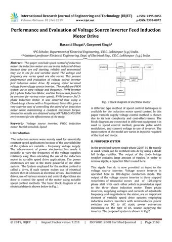
Fig:-1 Block diagram of electrical motor A different type method of speed control techniques is available for the induction motor speed control. In this paper variable supply voltage control method is chosen due to its less complexity and cost-effectiveness. The block diagram are connected in different equipment it is used to speed control method, generate pulse width modulation, and convert voltage to use of inverter. The input system of the model are varies in input to required of the load and motor.
Keyword;- Voltage source inverter, PWM, Induction motor, Matlab simulink, Speed I. Introduction The induction motors were mainly used for essentially constant speed applications because of the unavailability of the system are variable – frequency voltage supply. The advancement of power electronics has made it possible to vary the frequency of the voltage supplies relatively easy, thus extending the use of the induction motor in variable speed drive applications. The power electronics are use in the more powerful of the other system. The System employed for the motion control is called a drive, if such system makes use of electrical motors then it is known as electrical drives. . In electrical drives, use of various sensors and control algorithms are done to control the speed of the motor using suitable speed control methods. The basic block diagram of an electrical drive is shown below in Fig .1
Š 2019, IRJET
|
Impact Factor value: 7.211
II. PROPOSED SYSTEM In the proposed system single phase 220V, 50 Hz supply is used, which can be rectified into dc by using a diode full bridge rectifier. The output of the diode bridge rectifier contains large amount of ripples. In order to remove ripple, a capacitor filter is used here: This ripple free dc is now provided as input to the voltage source inverter. Voltage source inverter is operated here in 180-degree conduction mode. The output of the voltage source inverter is three stepped waveforms of sinusoidal waves and of 120-degree phase shift with each other ,which is provided as input to the three phase induction motor. Three phase inverters, supplying voltages and currents of adjustable frequency and magnitude to the stator, are an important element of variable speed drive systems employing induction motors. Inverters with semiconductor power switches are DC to AC static power converters Depending on the type of DC source supplying the inverter. The proposed system is shown in Fig.2
|
ISO 9001:2008 Certified Journal
|
Page 1168