International Research Journal of Engineering and Technology (IRJET)
e-ISSN: 2395-0056
Volume: 05 Issue: 06 | JUNE 2018
p-ISSN: 2395-0072
www.irjet.net
Three Phase Interleaved Boost Converter Prachi Shinde1, Pradnya Ravindra Narvekar2, Mahesh Manik Kumbhar3 1,2Assistant
Professor, Department of E&TC, SGI, Institutes, Atigre, Maharashtra, India Professor, Department of E&TC, ADCET, Ashta, Maharashtra, India ---------------------------------------------------------------------***--------------------------------------------------------------------3Assistant
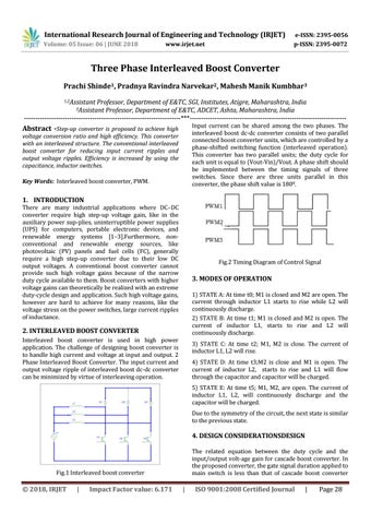
Input current can be shared among the two phases. The interleaved boost dc-dc converter consists of two parallel connected boost converter units, which are controlled by a phase-shifted switching function (interleaved operation). This converter has two parallel units; the duty cycle for each unit is equal to (Vout-Vin)/Vout. A phase shift should be implemented between the timing signals of three switches. Since there are three units parallel in this converter, the phase shift value is 1800.
Abstract -Step-up converter is proposed to achieve high
voltage conversion ratio and high efficiency. This converter with an interleaved structure. The conventional interleaved boost converter for reducing input current ripples and output voltage ripples. Efficiency is increased by using the capacitance, inductor switches. Key Words: Interleaved boost converter, PWM.
1. INTRODUCTION
There are many industrial applications where DC–DC converter require high step-up voltage gain, like in the auxiliary power sup-plies, uninterruptible power supplies (UPS) for computers, portable electronic devices, and renewable energy systems [1–3].Furthermore, nonconventional and renewable energy sources, like photovoltaic (PV) panels and fuel cells (FC), generally require a high step-up converter due to their low DC output voltages. A conventional boost converter cannot provide such high voltage gains because of the narrow duty cycle available to them. Boost converters with higher voltage gains can theoretically be realized with an extreme duty-cycle design and application. Such high voltage gains, however are hard to achieve for many reasons, like the voltage stress on the power switches, large current ripples of inductance.
Fig.2 Timing Diagram of Control Signal
3. MODES OF OPERATION 1) STATE A: At time t0; M1 is closed and M2 are open. The current through inductor L1 starts to rise while L2 will continuously discharge. 2) STATE B: At time t1; M1 is closed and M2 is open. The current of inductor L1, starts to rise and L2 will continuously discharge.
2. INTERLEAVED BOOST CONVERTER Interleaved boost converter is used in high power application. The challenge of designing boost converter is to handle high current and voltage at input and output. 2 Phase Interleaved Boost Converter. The input current and output voltage ripple of interleaved boost dc-dc converter can be minimized by virtue of interleaving operation.
3) STATE C: At time t2; M1, M2 is close. The current of inductor L1, L2 will rise. 4) STATE D: At time t3;M2 is close and M1 is open. The current of inductor L2, starts to rise and L1 will flow through the capacitor and capacitor will be charged. 5) STATE E: At time t5; M1, M2, are open. The current of inductor L1, L2, will continuously discharge and the capacitor will be charged. Due to the symmetry of the circuit, the next state is similar to the previous state.
4. DESIGN CONSIDERATIONSDESIGN The related equation between the duty cycle and the input/output volt-age gain for cascade boost converter. In the proposed converter, the gate signal duration applied to main switch is less than that of cascade boost converter
Fig.1 Interleaved boost converter
© 2018, IRJET
|
Impact Factor value: 6.171
|
ISO 9001:2008 Certified Journal
|
Page 28