International Research Journal of Engineering and Technology (IRJET)
e-ISSN: 2395 -0056
Volume: 04 Issue: 05 | May -2017
p-ISSN: 2395-0072
www.irjet.net
PHYSICAL SYSTEM ANALYSIS USING MATLAB Anchal Khandelwal , Harish Sharma M. Tech Scholar, Department of Electronics and Communication Engineering, Government Engineering College Ajmer Assistant Professor , Department of Electronics and Communication Engineering , Government Engineering College, Ajmer ---------------------------------------------------------------------***--------------------------------------------------------------------Abstract - An important parameter of any system is its stability which is defined with the help of poles. If the transfer function of a system is available its poles and zeros can be find out easily. Then it is also possible to define delay and gain parameters of the system. The transfer function is usually derived using either poles and zeros or numerators and denominators. Here the transfer function of a physical system is derived using input and output streams. Any Physical system like motor, filter etc., is fed with the input signal, with help of “stm32f407” processor and thus we got the corresponding output using ADC that fed to computer via UART. In this contribution high pass filter used as a physical system, fed with square wave as a input signal and obtained the corresponding output. After importing these input and output streams in MATLAB the transfer function is plotted, thus defining various parameters of the system.
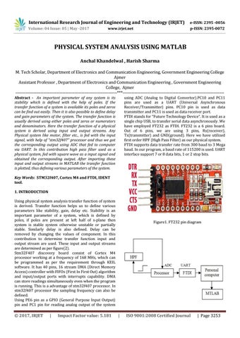
using ADC (Analog to Digital Convertor).PC10 and PC11 pins are used as a UART (Universal Asynchronous Receiver/Transmitter) pins. PC10 pin is used as data transmitter and PC11 is used as data receiver port. FTDI stands for “Future Technology Device”. It is used as a single chip USB, to transfer serial data asynchronously .We have employed FT232 as FTDI. FT232 is a 6 pins board. Out of 6 pins, we are using 3 pins, Rx(receiver), Tx(transmitter) and GND(ground). Here we have utilized first order HPF (High Pass Filter) as our physical system. FTDI supports data transfer rate from 300 baud to 3 Mega baud. In our program, a baud rate of 115200 is used. UART interface support 7 or 8 data bits, 1 or 2 stop bits.
Key Words: STM32f407, Cortex M4 and FTDI, IDENT tool. 1. INTRODUCTION Using physical system analysis transfer function of system is derived. Transfer function helps us to define various parameters like stability, gain, delay etc. Stability is an important parameter of a system, which is defined by poles, if poles are present at left half of s-plane then system is stable system otherwise unstable or partially stable. Similarly delay is also defined. Delay can be removed by changing the values of component. In this contribution to determine transfer function input and output stream are used. These input and output streams are determined as per figure(2). Stm32F407 discovery board consist of Cortex M4 processor working at a frequency of 168 MHz, which can be programmed as per the requirement through KEIL software. It has 40 pins, 16 stream DMA (Direct Memory Access) controller with FIFOs (First In First Out) algorithm and input/output ports with interrupts capability. DMA can store readings simultaneously even when the program is running. This is a advantage of stm32f407 processor. In stm32f407 processor the sampling frequency can also be defined. Using PE6 pin as a GPIO (General Purpose Input Output) pin and PC1 pin for reading analog output of the system
© 2017, IRJET
|
Impact Factor value: 5.181
Figure1. FT232 pin diagram
|
ISO 9001:2008 Certified Journal
| Page 3253