International Research Journal of Engineering and Technology (IRJET)
e-ISSN: 2395 -0056
Volume: 04 Issue: 05 | May -2017
p-ISSN: 2395-0072
www.irjet.net
Comparative Harmonic Analysis of a 3-Phase Bridge Type Inverter Operating at different Conduction Mode using RL-Load Ankit .S. Makwana1 1Student,Electrical
Engineering Department, Sardar Vallabhbhai Patel Institute of Technology,Vasad,Gujarat,India ---------------------------------------------------------------------***---------------------------------------------------------------------
Impact Factor value: 5.181
|
B
#1
#2
2 g1
I1
Ea B
I3 D 2 g3
I5 D 2 g5
Eo
R=0
A
C
11 [kV]
C 415 [V] 4
6
I4 D
2 2 g4
I6 D 2 g6
I2 D 2 g2
30 [ohm]
|
B
A
50 [kVA]
I1 D
5
30 [ohm]
© 2017, IRJET
A
C
3
30 [ohm]
There are two types of power topologies in inverter, namely Voltage Source Inverter and Current Source Inverter which is further classified as single phase inverter and three phase inverter. Three phase inverter can be operated in three different conduction modes i.e. 180 °, 120° and 150° conduction mode. Use of inverters in power system creates harmonics which are harmful to the system. So to mitigate harmonics from the system, improved controlling techniques and PWM technique are used. The variable output voltage and reduction in harmonics can be obtained operating at different conduction modes of 3 phase inverter. From this discussion comparison topics are achieved. This paper focuses on of 3 phase bridge type voltage source inverter of a
1
IA
Generating electricity from renewable natural resources like wind and sun etc. are commonly used in order to fulfil the increased power demand. Harnessing electrical energy from natural resources is not easy and cannot be used directly to power the load. To do so, power electronic converters are used. Thus it becomes important to design these converters optimally in order to provide high efficiency and reliability of the system. Inverters has wide range of applications, from small switching power supplies, to large electric power utility using HVDC system to transmit bulk power at a high voltage to a far distance. A power electronics inverter is widely used as D.C to A.C converter in VFD at desired frequency and voltage.
10 [mH]
1. INTRODUCTION
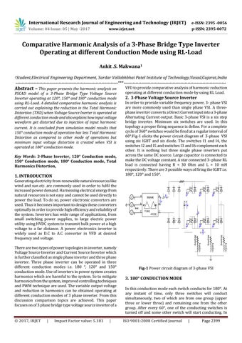
In order to provide variable frequency power, 3- phase VSI are more commonly used than single phase VSI. A threephase inverter converts a Direct Current input into a 3-phase Alternating Current output. Basic 3-phase VSI is a six step bridge inverter. Minimum six switches are used. In this topology a proper firing sequence is define. For a complete cycle of 360° switches would be fired at a regular interval of 60°.Fig-1 elicits the power circuit diagram of 3-phase VSI using six IGBT and six diode. The switches I1 and I4, the switches I2 and I5 and switches I3 and I6 complement each other. It is nothing but three single phase inverters put across the same DC source. Large capacitor is connected to make the DC voltage constant. A star connected 3- phase RL load is connected having R = 30 Ohm and L = 10 mH respectively. There are 3 possible ways of firing the IGBT i.e. 180°, 120° and 150°.
10 [mH]
Key Words: 3-Phase Inverter, 120° Conduction mode, 150° Conduction mode, 180° Conduction mode, Total Harmonics Distortion,
2. 3-Phase Voltage Source Inverter
VAB
PSCAD model of a 3-Phase Bridge Type Voltage Source Inverter operating at 120°, 150° and 180° conduction mode using RL-Load. A detailed comparative harmonic analysis is carried out explaining the reduction in the Total Harmonic Distortion (THD) when Voltage Source Inerter is operated at different conduction mode and also explains how input voltage waveform get distorted due to injection of input harmonic current. It is concluded from simulation model results that 150° conduction mode of operation has less Total Harmonic Distortion as compared to other mode of operations but minimum input voltage distortion is created when VSI is operated at 180° conduction mode.
VFD to provide comparative analysis of harmonic reduction operating at different conduction mode by using RL Load.
10 [mH]
Abstract – This paper presents the harmonic analysis on
Fig-1 Power circuit diagram of 3-phase VSI
3. 180° CONDUCTION MODE In this conduction mode each switch conducts for 180°. At any instant of time, only three switches will conduct simultaneously, two of which are from one group (upper three or lower three) and remaining one from the other group. After every 60°, one of the conducting switches is turned off and some other switch will start conducting. In ISO 9001:2008 Certified Journal
|
Page 2399