International Research Journal of Engineering and Technology (IRJET)
e-ISSN: 2395 -0056
Volume: 04 Issue: 05 | May -2017
p-ISSN: 2395-0072
www.irjet.net
DS-UWB signal generator for RAKE receiver with optimize selection of pulse width Twinkle V. Doshi EC department, BIT, Vadodara, Gujarat, India ---------------------------------------------------------------------***---------------------------------------------------------------------
Abstract -This paper presents discussion on the DS-UWB
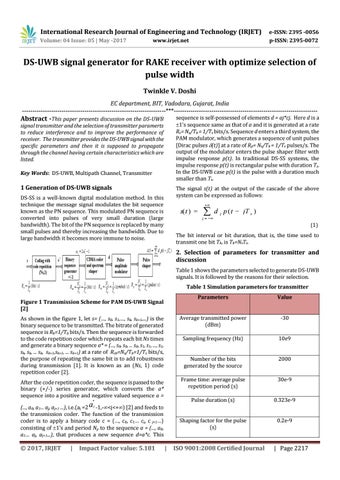
sequence is self-possessed of elements d = aj*cj. Here d is a 1’s sequence same as that of a and it is generated at a rate Rc= Ns/Tb = 1/Ts bits/s. Sequence d enters a third system, the PAM modulator, which generates a sequence of unit pulses [Dirac pulses (t)] at a rate of Rp= Ns/Tb = 1/Ts pulses/s. The output of the modulator enters the pulse shaper filter with impulse response p(t). In traditional DS-SS systems, the impulse response p(t) is rectangular pulse with duration Ts. In the DS-UWB case p(t) is the pulse with a duration much smaller than Ts.
signal transmitter and the selection of transmitter paramerts to reduce interference and to improve the performance of receiver. The transmitter provides the DS-UWB signal with the specific parameters and then it is supposed to propagate through the channel having certain characteristics which are listed. Key Words: DS-UWB, Multipath Channel, Transmitter
1 Generation of DS-UWB signals
The signal s(t) at the output of the cascade of the above system can be expressed as follows:
DS-SS is a well-known digital modulation method. In this technique the message signal modulates the bit sequence known as the PN sequence. This modulated PN sequence is converted into pulses of very small duration (large bandwidth). The bit of the PN sequence is replaced by many small pulses and thereby increasing the bandwidth. Due to large bandwidth it becomes more immune to noise.
s( t )
j
d j p ( t jT s ) (1)
The bit interval or bit duration, that is, the time used to transmit one bit Tb, is Tb=NsTs.
2. Selection of parameters for transmitter and discussion Table 1 shows the parameters selected to generate DS-UWB signals. It is followed by the reasons for their selection. Table 1 Simulation parameters for transmitter Parameters
Value
As shown in the figure 1, let s= (…, s0, s1,…, sk, sk+1,...) is the binary sequence to be transmitted. The bitrate of generated sequence is Rb=1/Tb bits/s. Then the sequence is forwarded to the code repetition coder which repeats each bit Ns times and generate a binary sequence a* = (..., s0, s0, ... s0, s1, s1, ..., s1, sk, sk, ... sk, sk+1,sk+1, ... sk+1) at a rate of Rcb=Ns/Tb=1/Ts bits/s, the purpose of repeating the same bit is to add robustness during transmission [1]. It is known as an (Ns, 1) code repetition coder [2].
Average transmitted power (dBm)
-30
Sampling frequency (Hz)
10e9
Number of the bits generated by the source
2000
After the code repetition coder, the sequence is passed to the binary (+/-) series generator, which converts the a* sequence into a positive and negative valued sequence a =
Frame time: average pulse repetition period (s)
30e-9
Pulse duration (s)
0.323e-9
Shaping factor for the pulse (s)
0.2e-9
Figure 1 Transmission Scheme for PAM DS-UWB Signal [2]
*
(..., a0, a1... aj, aj+1 ...), i.e.(aj =2 a j -1,-<j<+) [2] and feeds to the transmission coder. The function of the transmission coder is to apply a binary code c = (…, c0, c1… cj, c j+1…) consisting of 1’s and period Np to the sequence a = (..., a0, a1… aj, aj+1...), that produces a new sequence d=a*c. This
© 2017, IRJET
|
Impact Factor value: 5.181
|
ISO 9001:2008 Certified Journal
| Page 2217