International Research Journal of Engineering and Technology (IRJET)
e-ISSN: 2395 -0056
Volume: 04 Issue: 05 | May -2017
p-ISSN: 2395-0072
www.irjet.net
Bending and Wear Analysis of Spur Gear Dr.Rupesh Bhortake1, Vaibhav Kharabe2, Kiran Shende2, Rohan Kadam2 1
Professor, Department of Mechanical Engineering, P.V.P.I.T, Bavdhan, Pune, India-411021. Student, Department of Mechanical Engineering, P.V.P.I.T, Bavdhan, Pune, India-411021.
2
---------------------------------------------------------------------***---------------------------------------------------------------------
Abstract - Gear are the fundamental components in
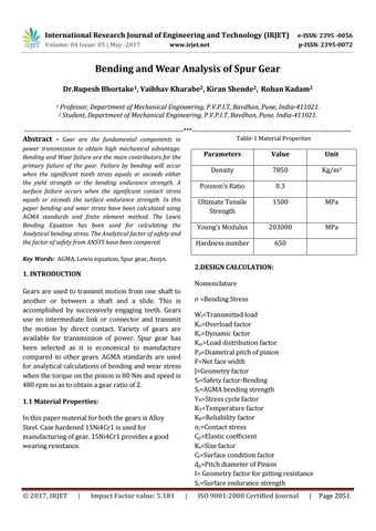
Table-1 Material Properties
power transmission to obtain high mechanical advantage. Bending and Wear failure are the main contributors for the primary failure of the gear. Failure by bending will occur when the significant tooth stress equals or exceeds either the yield strength or the bending endurance strength. A surface failure occurs when the significant contact stress equals or exceeds the surface endurance strength. In this paper bending and wear stress have been calculated using AGMA standards and finite element method. The Lewis Bending Equation has been used for calculating the Analytical bending stress. The Analytical factor of safety and the factor of safety from ANSYS have been compared.
Parameters
Value
Unit
Density
7850
Kg/m3
Poisson’s Ratio
0.3
Ultimate Tensile Strength
1500
MPa
Young’s Modulus
203000
MPa
Hardness number
650
Key Words: AGMA, Lewis equation, Spur gear, Ansys.
2.DESIGN CALCULATION:
1. INTRODUCTION
Nomenclature
Gears are used to transmit motion from one shaft to another or between a shaft and a slide. This is accomplished by successively engaging teeth. Gears use no intermediate link or connector and transmit the motion by direct contact. Variety of gears are available for transmission of power. Spur gear has been selected as it is economical to manufacture compared to other gears. AGMA standards are used for analytical calculations of bending and wear stress when the torque on the pinion is 80 Nm and speed is 480 rpm so as to obtain a gear ratio of 2.
σ =Bending Stress Wt=Transmitted load Ko=Overload factor Kv=Dynamic factor Km=Load distribution factor Pd=Diametral pitch of pinion F=Net face width J=Geometry factor Sf=Safety factor-Bending St=AGMA bending strength YN=Stress cycle factor KT=Temperature factor KR=Reliability factor σc=Contact stress Cp=Elastic coefficient Ks=Size factor Cf=Surface condition factor dp=Pitch diameter of Pinion I= Geometry factor for pitting resistance Sc=Surface endurance strength
1.1 Material Properties: In this paper material for both the gears is Alloy Steel. Case hardened 15Ni4Cr1 is used for manufacturing of gear. 15Ni4Cr1 provides a good wearing resistance.
© 2017, IRJET
|
Impact Factor value: 5.181
|
ISO 9001:2008 Certified Journal
|
Page 2051