International Research Journal of Engineering and Technology (IRJET)
e-ISSN: 2395 -0056
Volume: 04 Issue: 05 | May -2017
p-ISSN: 2395-0072
www.irjet.net
Verilog Based Behavioral Modeling Multi Master I2C Bus Controller Ameerbasha Dudekula 15G81D5709,SKDEC,Gooty.
Mrudula S Asst. Professor,(Guide)
Geetha K
Dr.Ramachandra Rao
Professor,(HOD)
Principal,SKDEC,Gooty.
---------------------------------------------------------------------***--------------------------------------------------------------------using C Bus. It gives an idea about C Master Controller pin Abstract: This paper presents design and implementation of
level architecture. In this paper, we are implementing Multi – Master C Bus Controller in various speed modes. Among all the speed modes throughput is found to be good in the High Speed Mode. The synopsis of the paper is as follows: In section II, we discussed C Bus Specifications, in Section III, we had given proposed work which also includes various I2C Bus Characterstics and Bus Architectures, in Section IV, we di scussed about the designing of C Master Controller, in Section V, we posted the simulation and synthesis results, in Section VI, conclusions are drawn based on the results and future scope is discussed in brief.
Multi – Master Inter – Integrated Circuit (often written as or IIC) Bus Controller. The Multi – Master C Bus Interface is a circuit to perform serial communication based on data format transfer. The arbitration lost detect function makes multi master communication possible. The communication is done on four modes of data transfer depending on the application. Ihe module was designed in Verilog HDL. It is simulated and synthesized using Xilinx Design Suite 13.2 Index Terms-C, Master, Serial data communication, Slave, Xilinx.
I.INTRODUCTION
II.C BUS SPECIFICATIONS
In serial data communication, there are many protocols like RS-232, RS-422, RS-485, SPI (Serial peripheral interface), Micro wire for interfacing high speed and low speed peripherals. These protocols requires more pin connection in IC(Integrated Circuit) for serial data communication to take place, as the physical size of IC have decreased over the years, we require less number of pin connections for serial data transfer to take place. USB/SPI/Microwire and mostly UARTS are all just point to point data transfer bus systems. These use techniques like multiplexing of the data paths and forwarding of messages to service multiple devices. To overcome this problem, the C protocol was introduced by Phillips. This protocol requires only two lines for communication with two or more chips and can control a network of device chips which has a two general purpose I/O pins whereas, other bus protocols require more pins and signals to connect devices. Bollam Eswari et al[1].,discussed the implementation of C Protocol on FPGA, it is given that C Master Controller transmits data to and from slave. Any low speed peripherals can be interfaced by using C Master Controller. J.J.Patel et al[2]., discussed the design and the implementation of C Bus Controller using Verilog, it gives an idea of C Bus Controller design which consists of start/stop control, Counter, Arbitration Unit, Microprocessor Interface, State machine, Interrupt Controller, Clock Generator and synchronizer. P.K.Mehto et. Al[3] discussed about the design and the
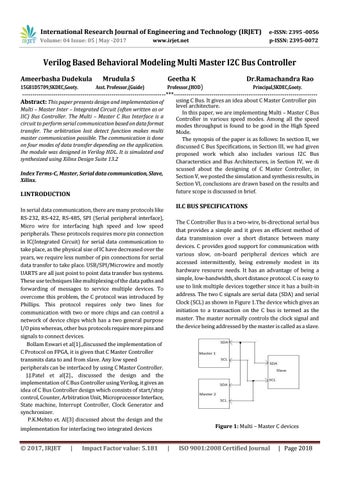
The C Controller Bus is a two-wire, bi-directional serial bus that provides a simple and it gives an efficient method of data transmission over a short distance between many devices. C provides good support for communication with various slow, on-board peripheral devices which are accessed intermittently, being extremely modest in its hardware resource needs. It has an advantage of being a simple, low-bandwidth, short distance protocol. C is easy to use to link multiple devices together since it has a built-in address. The two C signals are serial data (SDA) and serial Clock (SCL) as shown in Figure 1.The device which gives an initiation to a transaction on the C bus is termed as the master. The master normally controls the clock signal and the device being addressed by the master is called as a slave.
Figure 1: Multi – Master C devices
implementation for interfacing two integrated devices
© 2017, IRJET
|
Impact Factor value: 5.181
|
ISO 9001:2008 Certified Journal
| Page 2018