International Research Journal of Engineering and Technology (IRJET)
e-ISSN: 2395 -0056
Volume: 04 Issue: 05 | May -2017
p-ISSN: 2395-0072
www.irjet.net
LOW POWER BASED DUAL MODE LOGIC GATES USING POWER GATING TECHNIQUE Swapnil S. Patil1, Sagar S. Pathak2, Rahul R. Kathar3, D. S. Patil4 Pursuing M. Tech, Dept. of Electronics Engineering & Technology, NMU, Maharashtra, India. 4Professor, Dept. of Electronics and Engineering, NMU, Maharashtra, India ---------------------------------------------------------------------***--------------------------------------------------------------------123
Abstract - In this paper, we present the design and
enactment D- FLIP-FLOP, SR FLIP-FLOP, J-K FLIP-FLOP using dual mode logic with power gating procedures. This model is used for designing consecutive circuits whose circuit has been done in TANNER, the output waveform is displayed on W-EDIT and delay, average power calculations have been done for these circuits for value of supply i.e. 1.2V.it is use TSMC0.18 Technology. Key Words: D- FLIP-FLOP, SR FLIP-FLOP, J-K FLIP-FLOP, TANNER EDA TOOL
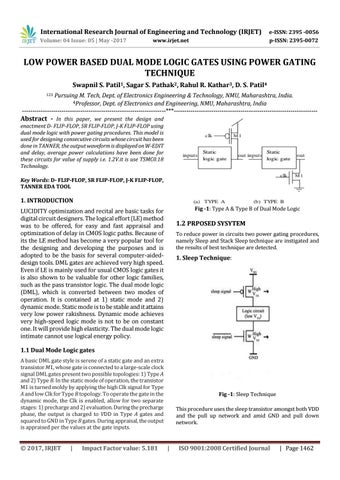
1. INTRODUCTION Fig -1: Type A & Type B of Dual Mode Logic
LUCIDITY optimization and recital are basic tasks for digital circuit designers. The logical effort (LE) method was to be offered, for easy and fast appraisal and optimization of delay in CMOS logic paths. Because of its the LE method has become a very popular tool for the designing and developing the purposes and is adopted to be the basis for several computer-aideddesign tools. DML gates are achieved very high speed. Even if LE is mainly used for usual CMOS logic gates it is also shown to be valuable for other logic families, such as the pass transistor logic. The dual mode logic (DML), which is converted between two modes of operation. It is contained at 1) static mode and 2) dynamic mode. Static mode is to be stable and it attains very low power rakishness. Dynamic mode achieves very high-speed logic mode is not to be on constant one. It will provide high elasticity. The dual mode logic intimate cannot use logical energy policy.
1.2 PRPOSED SYSYTEM To reduce power in circuits two power gating procedures, namely Sleep and Stack Sleep technique are instigated and the results of best technique are detected.
1. Sleep Technique:
1.1 Dual Mode Logic gates A basic DML gate style is serene of a static gate and an extra transistor M1, whose gate is connected to a large-scale clock signal DML gates present two possible topologies: 1) Type A and 2) Type B. In the static mode of operation, the transistor M1 is turned moldy by applying the high Clk signal for Type A and low Clk for Type B topology. To operate the gate in the dynamic mode, the Clk is enabled, allow for two separate stages: 1) precharge and 2) evaluation. During the precharge phase, the output is charged to VDD in Type A gates and squared to GND in Type B gates. During appraisal, the output is appraised per the values at the gate inputs.
Š 2017, IRJET
|
Impact Factor value: 5.181
Fig -1: Sleep Technique This procedure uses the sleep transistor amongst both VDD and the pull up network and amid GND and pull down network.
|
ISO 9001:2008 Certified Journal
| Page 1462