International Research Journal of Engineering and Technology (IRJET) Volume: 04 Issue: 05 | May -2017
www.irjet.net
e-ISSN: 2395 -0056 p-ISSN: 2395-0072
REDUCING POWER, LEAKAGE AND AREA OF STANDARD CELL USING LECTOR STACK Ramya.M1, Shantha Devi.P2, Jeyashri.M 3 ,Devi.P4 123PG
Scholar, Department of ECE, Theni Kammavar Sangam Collage Of Technology, Tamilnadu, India. 4Assistant Professor, Department. of ECE, Theni Kammavar Sangam Collage Of Technology, Tamilnadu, India. ---------------------------------------------------------------------***--------------------------------------------------------------------2. NEW ARCHIT ECT URE FOR A THRESHOL D Abstract: Dynamic power, spillage, and area are the GAT E important factor of the ASIC. in this paper we decrease these factors using different approach .this approach depends on an outline of edge rationale entryways (TLGs), it was jointed with customary standard-cell configuration stream. The edge entryway acts as a multi-input, single output, edge-activated flip flounder, which controls the capacity during edge clocking. A little number of cells can register an arrangement of the capacities. For this the leakage current due to sub threshold voltage was reduce. The leakage power in digital circuits was unavoidable. So we use two techniques for reducing the leakage power which are Transistor stacking and selfadjustable voltage level circuit. In scaling technology, the power density increases 40% for every generation. So every design needs application and product based technique. Key Words: Logic decomposition, low power technology mapping, threshold logic, MTCMOS.
(LP),
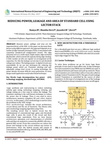
For a threshold gate here we use a different logic method that is used PNAND c e l l s w i t h d i f f e r e n t w a y s . Another way is used during clocking in PNAND cells referred as multiinput edge-triggered flip- flop.
2.1. Lector Technique: To solve these problems we go for lector logic Basic principle. It was used in stack effect only. In this technique two extra transistors (one PMOS and one NMOS) are used .it was placed between pull down and pull up network. These extra transistors are control their self so it was also called as Leakage Control Transistors (LCT). The gate of each Leakage Control Transistors is controlled by the source of other transistors. In this type of arrangement one of the Leakage Control Transistors always remains in its near cut off region.
1. INTRODUCTION Logic synthesis and restructuring to reduce switching activity, gate sizing, technology mapping, retiming, and voltage scaling are a few ways to reduce the leakage. The transistor stacking is the well-known technique to reduce the power due to leakage. Thus, it was used in micro architectures, memory, compilers, OS a n d o t h e r d i g i t a l c i r c u i t s . In this paper, a TLG methodology is used for solve the problems in the ASIC design. T h i s m e t h o d o l o g y includes the circuit architecture, circuit library and the set of functions. The library cells, and a technology mapping algorithm using TLGs. The resulting circuit that is hybrid circuit has the combinational of conventional logic gates and threshold logic cells. It gives the result of the circuit and their conventional logic equivalents. First we have known architecture, operation, a n d characteristics o f p N A N D cells and then we analysis to connect the pNAND cells into a general ASIC circuit. From this connection we reduce the power and leakage in the circuit without any tenner in performance. Since the hybrid circuits will consist of conventional standard cells (e.g., NAN D, NOR, AOI, MUX, and so on) and pNAND cells.
Š 2017, IRJET
|
Impact Factor value: 5.181
|
`. FIG- 1: Architecture of PNAND Cell
ISO 9001:2008 Certified Journal
| Page 1079