International Research Journal of Engineering and Technology (IRJET)
e-ISSN: 2395 -0056
Volume: 04 Issue: 04 | Apr -2017
p-ISSN: 2395-0072
www.irjet.net
Maggneto Electricity Generator Shubham More, Satya Prakash T.E. Electrical, SKNSITS College of Engineering, STES Campus, Lonavala. Pune, Maharashtra, India Assistant Professor, SKNSITS College of Engineering, STES Campus Lonavala, Maharashtra, India ---------------------------------------------------------------------***--------------------------------------------------------------------2. COMPONENTS OF FREE ELECTRICITY Abstract - Until now the electricity generation is very costly GENERATOR: and energy wasting procedure. So an alternative to the
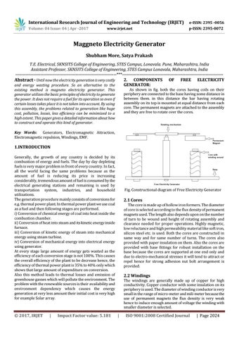
As shown in fig. both the cores having coils on their periphery are connected to the base having some distance in between them. in this distance the bar having rotating assembly on its top is mounted at equal distance from each core. The permanent magnets are attached to the assembly and they are free to rotate over the cores.
existing method is magneto electricity generator. This generator utilizes the basic principles of electricity to generate the power. It does not require a fuel for its operation so even if certain losses takes place it is not taken into account. By using this assembly, the problems related to generation like huge cost, pollution, losses, less efficiency can be minimized to a high extent. This paper gives a detailed information about how to construct and operate this kind of generator. Key Words: Generators, Electromagnetic Attraction, Electromagnetic repulsion, Windings, EMF.
1.INTRODUCTION Generally, the growth of any country is decided by its combustion of energy and fuels. The day by day depleting fuels is very major problem in front of every country. In fact, all the world facing the same problems because as the amount of fuel is reducing its price is increasing considerably, tremendous amount of fuel is consumed by the electrical generating stations and remaining is used by transportation system, industries, and household utilizations. The generation procedure mainly consists of conversions for e.g. thermal power plant. In thermal power plant we use coal as a fuel and then following stages are performed. i) Conversion of chemical energy of coal into heat inside the combustion chamber. ii) Conversion of heat into steam and its kinetic energy inside furnace. iii) Conversion of kinetic energy of steam into mechanical energy using steam turbine. iv) Conversion of mechanical energy into electrical energy using generator. At every stage large amount of energy gets wasted as the efficiency of each conversion stage is not 100%. This causes the overall efficiency of the plant to be decrease hence, the efficiency of thermal power plant is 35% to 40% only which shows that large amount of expenditure on conversion. Also this method leads to thermal losses and emission of greenhouse gasses which will pollute the environment. The problem with the renewable sources is their availability and environment dependency which causes the energy generation at very less amount their initial cost is very high for example Solar array.
Š 2017, IRJET
|
Impact Factor value: 5.181
Fig. Constructional diagram of Free Electricity Generator
2.1 Cores
The core is made up of hollow iron formers. The diameter of core is selected according to the flux density of permanent magnets used. The length also depends upon on the number of turn to be wound and height of rotating assembly and clearance needed for proper operations. Highly magnetic, low reluctance and high permeability material like soft iron, silicon steel etc. is used. Both the cores are constructed in same way and for same number of turns. The cores also provided with paper insulation on them. Also the cores are provided with base fittings for robust installation on the base because the cores are supported at one end only and due to electro-mechanical stresses it will tend to attract or repel hence for strong adhesion nut bolt arrangement is provided.
2.2 Windings
The windings are generally made up of copper for high conductivity. Copper conductor with some insulation on its periphery is used. The diameter of winding conductor is very small in the range of micro-meter and mili-meter because the use of permanent magnets the flux density is very weak hence to induce enough amount of voltage the winding with smaller diameter is selected.
|
ISO 9001:2008 Certified Journal
| Page 2024