International Research Journal of Engineering and Technology (IRJET)
e-ISSN: 2395 -0056
Volume: 03 Issue: 09 | Sep-2016
p-ISSN: 2395-0072
www.irjet.net
Power System Stability Using Unified Power Flow Controller Sonal M. Adhau1, Dinesh D.Majumdar2 Electrical Engineering Department ,Shri Sai College of Engineering & Technology Bhadrawati, Electrical Engineering Department ,Shri Sai College of Engineering & Technology Bhadrawati, Maharashtra (India). ---------------------------------------------------------------------***---------------------------------------------------------------------
Abstract - UPFC is one of the most widely used FACTS
devices. To control (Kw) and (Kvar) in power system FACTS devices are usually used. In this paper case study of 9 bus system is considered under the three phase to ground fault in MATLAB Simulink. Active power, reactive power and rotor angle, angular speed during the fault is analyzed. Key Words: MATLAB-Simulink, UPFC
2. ASSUMPTION IN TRANSIENT STABILITY I) Mechanical input given to the synchronous generator will be constant. II) Effect of damper winding can be neglected. III) The voltage at generator and at the bus are assumed to be constant. IV) Angular velocity of synchronous machine will be assumed as constant.
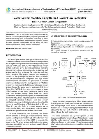
1.INTRODUCTION In recent year the technology is advances so that transmission network reliable and easy to design. There are many technologies in interconnected power system such as, HVDC and EHVAC. On other side as power system network grow, the interconnected network become increasingly more composite to operate and system can be less protected for riding through the major outages. The power system interconnected network of today is large and complex. There is widely use of microelectronic, computers and high speed communication for control and protection of present interconnected system. The main purpose of FACTS is to improve system controllability and to increase power system bound by using power automated devices. Generally, FACTS devices are more expensive than HVDC devices. In case study consists of 3 generators nine bus system having three load and three transformer. The single line diagram of nine bus system as shown in fig. 1.It is simple diagram of power system to analyzed dynamic behavior and also power oscillation damping. In this system three phase fault is occurs at bus 8.Duration of fault time is 4 to 4.1 sec. After 4.1 sec. the fault is remove system try to maintained stability, also active power, reactive power and bus voltage of different buses is calculated. The UPFC consists of two branches. The series branch consists of a voltage source converter, which injects a voltage in series through a transformer. The inverter at the input end of the UPFC is connected in shunt to the AC power system and the inverter at the input end of the UPFC is connected in series with the AC transmission circuit. © 2016, IRJET
|
Impact Factor value: 4.45
|
Fig.1 Single Line Diagram of 9 Bus System
Single line diagram consist of 9 bus power system having generator, load, transformer and transmission line having length 50km. UPFC is connected between buses 7 and 5. Three phase to ground fault takes place at near to the bus no.4. Duration of fault is 0.1 sec. After 4.1 sec. the fault is removed. The main constraint in a power system i.e. line impedance (XL), terminal voltage (Vt) and rotor angle (δ). The performance of system is studied and damping of the oscillation in rotor angle (δ) and angular speed (dw) is investigated in the three machine of nine bus system.
ISO 9001:2008 Certified Journal
|
Page 1445