International Research Journal of Engineering and Technology (IRJET) Volume: 03 Issue: 08 |Aug -2016
www.irjet.net
e-ISSN: 2395 -0056 p-ISSN: 2395-0072
Five Level Inverter to reduce Harmonics Vijay Patil, Dr. V. V. Patil2 1Student,
Dr. J. J. Magdum College of Engineering, Jaysingpur Dr. J. J. Magdum College of Engineering, Jaysingpur
2Professor,
---------------------------------------------------------------------***---------------------------------------------------------------------
Abstract - With the development in controlling
technology, demand for the efficient power systems is increased in the market. It is difficult to achieve efficient power system by using traditional approach & arrangement of power component. Voltage converters, Inverters & UPS are most commonly used power sources. These sources mainly comprises of inverter block so demand for highly efficient, reliable and compact inverters is increasing in market. So as to achieve these requirements multi-level inverter technology are evolving. The multilevel inverters are suitable for various high voltage and high power applications due to their ability to synthesize waveforms with better harmonic spectrum , faithful output, size & efficiency . This paper deals with a five-level converter topology that follows this trend. In five-level, topologies and a theoretical power loss comparison as compare with two level inverter with the proposed solution is realized.
connected across conventional bridge & common point of diodes is connected to the midpoint of the dc link. Additional power switched are used to obtain different DC voltage levels. MATLAB/SIMULINK software is used to simulate five level & two level inverter topology.
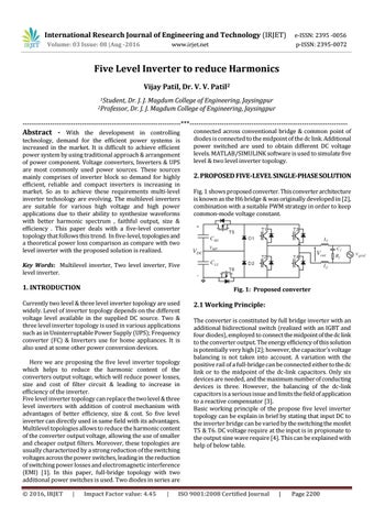
2. PROPOSED FIVE-LEVEL SINGLE-PHASE SOLUTION Fig. 1 shows proposed converter. This converter architecture is known as the H6 bridge & was originally developed in [2], combination with a suitable PWM strategy in order to keep common-mode voltage constant.
Key Words: Multilevel inverter, Two level inverter, Five level inverter.
1. INTRODUCTION
Fig. 1: Proposed converter
Currently two level & three level inverter topology are used widely. Level of inverter topology depends on the different voltage level available in the supplied DC source. Two & three level inverter topology is used in various applications such as in Uninterruptable Power Supply (UPS); Frequency converter (FC) & Inverters use for home appliances. It is also used at some other power conversion devices. Here we are proposing the five level inverter topology which helps to reduce the harmonic content of the converters output voltage, which will reduce power losses, size and cost of filter circuit & leading to increase in efficiency of the inverter. Five level inverter topology can replace the two level & three level inverters with addition of control mechanism with advantages of better efficiency, size & cost. So five level inverter can directly used in same field with its advantages. Multilevel topologies allows to reduce the harmonic content of the converter output voltage, allowing the use of smaller and cheaper output filters. Moreover, these topologies are usually characterized by a strong reduction of the switching voltages across the power switches, leading in the reduction of switching power losses and electromagnetic interference (EMI) [1]. In this paper, full-bridge topology with two additional power switches is used. Two diodes in series are Š 2016, IRJET
|
Impact Factor value: 4.45
|
2.1 Working Principle: The converter is constituted by full bridge inverter with an additional bidirectional switch (realized with an IGBT and four diodes), employed to connect the midpoint of the dc link to the converter output. The energy efficiency of this solution is potentially very high [2]; however, the capacitor’s voltage balancing is not taken into account. A variation with the positive rail of a full-bridge can be connected either to the dc link or to the midpoint of the dc-link capacitors. Only six devices are needed, and the maximum number of conducting devices is three. However, the balancing of the dc-link capacitors is a serious issue and limits the field of application to a reactive compensator [3]. Basic working principle of the propose five level inverter topology can be explain in brief by stating that input DC to the inverter bridge can be varied by the switching the mosfet T5 & T6. DC voltage require at the input is in propionate to the output sine wave require [4]. This can be explained with help of below table.
ISO 9001:2008 Certified Journal
|
Page 2200