International Research Journal of Engineering and Technology (IRJET)
e-ISSN: 2395 -0056
Volume: 03 Issue: 08 | Aug-2016
p-ISSN: 2395-0072
www.irjet.net
Influence of Cracks on Shaft: A Review Suhas S Jadhav1, Sushant S Jadhav2, Sumit B Sharma3 1Asstt.Prof.
Dept. of Mechanical Engineering, M.E.S. College of Engg. Pune-01. Dept. of Mechanical Engineering, M.E.S. College of Engg. Pune-01. 3Asso. Prof. Dept. of Applied Science, M.E.S. College of Engg. Pune-01.
2Asstt.Prof.
---------------------------------------------------------------------***--------------------------------------------------------------------2. FRACTURE MECHANICS AND FATIGUE
Abstract- Cracks are a threat to uninterrupted operation
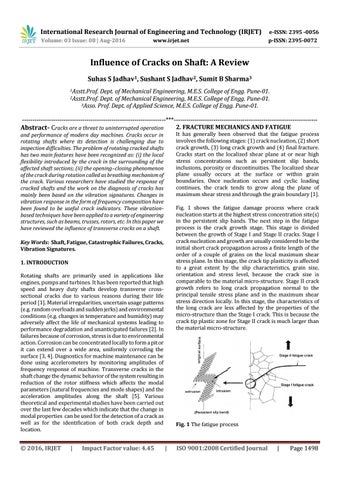
It has generally been observed that the fatigue process involves the following stages: (1) crack nucleation, (2) short crack growth, (3) long crack growth and (4) final fracture. Cracks start on the localized shear plane at or near high stress concentrations such as persistent slip bands, inclusions, porosity or discontinuities. The localized shear plane usually occurs at the surface or within grain boundaries. Once nucleation occurs and cyclic loading continues, the crack tends to grow along the plane of maximum shear stress and through the grain boundary [1].
and performance of modern day machines. Cracks occur in rotating shafts where its detection is challenging due to inspection difficulties. The problem of rotating cracked shafts has two main features have been recognized as: (i) the local flexibility introduced by the crack in the surrounding of the affected shaft sections; (ii) the opening–closing phenomenon of the crack during rotation called as breathing mechanism of the crack. Various researchers have studied the response of cracked shafts and the work on the diagnosis of cracks has mainly been based on the vibration signatures. Changes in vibration response in the form of frequency composition have been found to be useful crack indicators. These vibrationbased techniques have been applied to a variety of engineering structures, such as beams, trusses, rotors, etc. In this paper we have reviewed the influence of transverse cracks on a shaft.
Fig. 1 shows the fatigue damage process where crack nucleation starts at the highest stress concentration site(s) in the persistent slip bands. The next step in the fatigue process is the crack growth stage. This stage is divided between the growth of Stage I and Stage II cracks. Stage I crack nucleation and growth are usually considered to be the initial short crack propagation across a finite length of the order of a couple of grains on the local maximum shear stress plane. In this stage, the crack tip plasticity is affected to a great extent by the slip characteristics, grain size, orientation and stress level, because the crack size is comparable to the material micro-structure. Stage II crack growth refers to long crack propagation normal to the principal tensile stress plane and in the maximum shear stress direction locally. In this stage, the characteristics of the long crack are less affected by the properties of the micro-structure than the Stage I crack. This is because the crack tip plastic zone for Stage II crack is much larger than the material micro-structure.
Key Words: Shaft, Fatigue, Catastrophic Failures, Cracks, Vibration Signatures. 1. INTRODUCTION Rotating shafts are primarily used in applications like engines, pumps and turbines. It has been reported that high speed and heavy duty shafts develop transverse crosssectional cracks due to various reasons during their life period [1]. Material irregularities, uncertain usage patterns (e.g. random overloads and sudden jerks) and environmental conditions (e.g. changes in temperature and humidity) may adversely affect the life of mechanical systems leading to performance degradation and unanticipated failures [2]. In failures because of corrosion, stress is due to environmental action. Corrosion can be concentrated locally to form a pit or it can extend over a wide area, uniformly corroding the surface [3, 4]. Diagnostics for machine maintenance can be done using accelerometers by monitoring amplitudes of frequency response of machine. Transverse cracks in the shaft change the dynamic behavior of the system resulting in reduction of the rotor stiffness which affects the modal parameters (natural frequencies and mode shapes) and the acceleration amplitudes along the shaft [5]. Various theoretical and experimental studies have been carried out over the last few decades which indicate that the change in modal properties can be used for the detection of a crack as well as for the identification of both crack depth and location.
Š 2016, IRJET
|
Impact Factor value: 4.45
Fig. 1 The fatigue process
|
ISO 9001:2008 Certified Journal
|
Page 1498