International Research Journal of Engineering and Technology (IRJET) Volume: 03 Issue: 07 | July-2016
www.irjet.net
e-ISSN: 2395 -0056 p-ISSN: 2395-0072
Well Trajectory Survey of a Directional well Anurag Krishnan1, Prof. Avinash Kulkarni2 1ME
2ndyear, Department of Petroleum Engineering, Maharashtra Institute of Technology, Pune, India Professor, Department of Petroleum Engineering, Maharashtra Institute of Technology, Pune, India
2 Assistant
---------------------------------------------------------------------***---------------------------------------------------------------------
Abstract - Directional drilling has become a very important
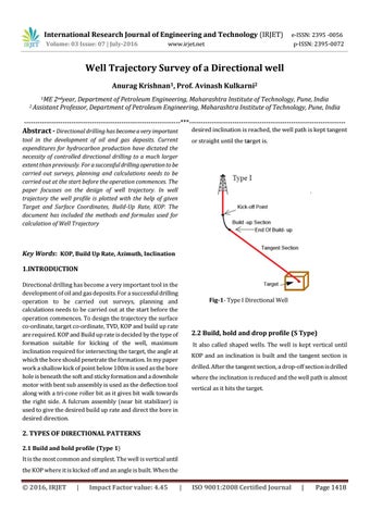
desired inclination is reached, the well path is kept tangent
tool in the development of oil and gas deposits. Current expenditures for hydrocarbon production have dictated the necessity of controlled directional drilling to a much larger extent than previously. For a successful drilling operation to be carried out surveys, planning and calculations needs to be carried out at the start before the operation commences. The paper focusses on the design of well trajectory. In well trajectory the well profile is plotted with the help of given Target and Surface Coordinates, Build-Up Rate, KOP. The document has included the methods and formulas used for calculation of Well Trajectory
or straight until the target is.
Key Words: KOP, Build Up Rate, Azimuth, Inclination 1.INTRODUCTION Directional drilling has become a very important tool in the development of oil and gas deposits. For a successful drilling operation to be carried out surveys, planning and calculations needs to be carried out at the start before the operation commences. To design the trajectory the surface co-ordinate, target co-ordinate, TVD, KOP and build up rate are required. KOP and Build up rate is decided by the type of formation suitable for kicking of the well, maximum inclination required for intersecting the target, the angle at which the bore should penetrate the formation. In my paper work a shallow kick of point below 100m is used as the bore hole is beneath the soft and sticky formation and a downhole motor with bent sub assembly is used as the deflection tool along with a tri-cone roller bit as it gives bit walk towards the right side. A fulcrum assembly (near bit stabilizer) is used to give the desired build up rate and direct the bore in desired direction.
Fig-1- Type I Directional Well
2.2 Build, hold and drop profile (S Type) It also called shaped wells. The well is kept vertical until KOP and an inclination is built and the tangent section is drilled. After the tangent section, a drop-off section is drilled where the inclination is reduced and the well path is almost vertical as it hits the target.
2. TYPES OF DIRECTIONAL PATTERNS 2.1 Build and hold profile (Type 1) It is the most common and simplest. The well is vertical until the KOP where it is kicked off and an angle is built. When the
Š 2016, IRJET
|
Impact Factor value: 4.45
|
ISO 9001:2008 Certified Journal
|
Page 1418