International Research Journal of Engineering and Technology (IRJET) Volume: 03 Issue: 07 | July-2016
www.irjet.net
e-ISSN: 2395 -0056 p-ISSN: 2395-0072
DESIGN AND ANALYSIS OF TELESCOPIC JACK Ashish Patil1, Sachin Wangikar2, Sangam Patil3, Rajashekhar M S4 Assistant Professor, Mechanical Department, Shaikh College of Engineering and Technology, karnataka, India Assistant Professor, Mechanical Department, Shaikh College of Engineering and Technology, karnataka, India 3 Assistant Professor, Mechanical Department, Shaikh College of Engineering and Technology, karnataka, India 4Assistant Professor, Mechanical Department, Shaikh College of Engineering and Technology, karnataka, India 1 2
---------------------------------------------------------------------***---------------------------------------------------------------------
Abstract - The use of hydraulic jack in the industry is
cylinders, the greater the increase in the force will be. A hydraulic jack operates based on this two cylinder system.
widespread as load lifting structures. Telescopic hydraulic jack is a special design of jack with a series of tubes of progressively smaller diameters nested within each other. They have long stroke from a compact initial package, which have attracted a lot of attention for their applications as load lifting structures.
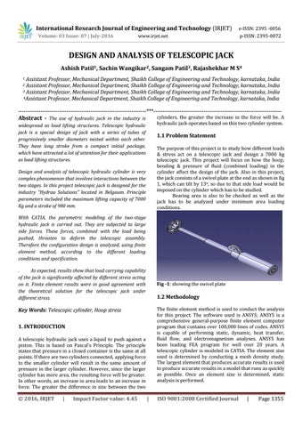
1.1 Problem Statement The purpose of this project is to study how different loads & stress act on a telescopic jack and design a 7000 kg telescopic jack. This project will focus on how the hoop, bending & pressure of fluid (combined loading) in the cylinder affect the design of the jack. Also in this project, the jack consists of a swivel plate at the end as shown in fig 1, which can tilt by 13o, so due to that side load would be imposed on the cylinder which has to be studied. Bearing area is also to be checked as well as the jack has to be analyzed under minimum area loading conditions.
Design and analysis of telescopic hydraulic cylinder is very complex phenomenon that involves interactions between the two stages. In this project telescopic jack is designed for the industry “Hydrau Solutions” located in Belgaum. Principle parameters included the maximum lifting capacity of 7000 Kg and a stroke of 980 mm. With CATIA, the parametric modeling of the two-stage hydraulic jack is carried out. They are subjected to large side forces. These forces, combined with the load being pushed, threaten to deform the telescopic assembly. Therefore the configuration design is analyzed, using finite element method, according to the different loading conditions and specification. . As expected, results show that load carrying capability of the jack is significantly affected by different stress acting on it. Finite element results were in good agreement with the theoretical solution for the telescopic jack under different stress.
Fig -1: showing the swivel plate
1.2 Methodology The finite element method is used to conduct the analysis for this project. The software used is ANSYS; ANSYS is a comprehensive general-purpose finite element computer program that contains over 100,000 lines of codes. ANSYS is capable of performing static, dynamic, heat transfer, fluid flow, and electromagnetism analyses. ANSYS has been leading FEA program for well over 20 years. A telescopic cylinder is modeled in CATIA. The element size used is determined by conducting a mesh density study. The largest element that produces accurate results is used to produce accurate results in a model that runs as quickly as possible. Once an element size is determined, static analysis is performed.
Key Words: Telescopic cylinder, Hoop stress 1. INTRODUCTION A telescopic hydraulic jack uses a liquid to push against a piston. This is based on Pascal’s Principle. The principle states that pressure in a closed container is the same at all points. If there are two cylinders connected, applying force to the smaller cylinder will result in the same amount of pressure in the larger cylinder. However, since the larger cylinder has more area, the resulting force will be greater. In other words, an increase in area leads to an increase in force. The greater the difference in size between the two
© 2016, IRJET
|
Impact Factor value: 4.45
|
ISO 9001:2008 Certified Journal
|
Page 1355