International Research Journal of Engineering and Technology (IRJET)
e-ISSN: 2395 -0056
Volume: 03 Issue: 03 | Mar-2016
p-ISSN: 2395-0072
www.irjet.net
Design of Intelligent Charger for Electric Vehicles Rahul A. Jagtap1, Dr. P.M. Daigavane 2, Dr.S.G. Tarnekar 3 1
4thSem student, M.tech (PED), Dept. of Electrical Engg GHRCE, Nagpur(India) 2 Head of Department, Dept. of Electrical Engg GHRCE, Nagpur(India) . 3 Professor, Dept. of Electrical Engg GHRCE, Nagpur(India)
---------------------------------------------------------------------***---------------------------------------------------------------------
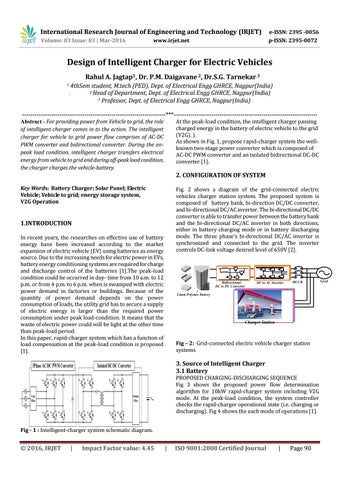
Abstract - For providing power from Vehicle to grid, the role of intelligent charger comes in to the action. The intelligent charger for vehicle to grid power flow comprises of AC-DC PWM converter and bidirectional converter. During the onpeak load condition, intelligent charger transfers electrical energy from vehicle to grid and during off-peak load condition, the charger charges the vehicle-battery.
At the peak-load condition, the intelligent charger passing charged energy in the battery of electric vehicle to the grid (V2G). ). As shown in Fig. 1, propose rapid-charger system the wellknown two-stage power converter which is composed of AC-DC PWM converter and an isolated bidirectional DC-DC converter [1].
2. CONFIGURATION OF SYSTEM Key Words: Battery Charger; Solar Panel; Electric Vehicle; Vehicle to grid; energy storage system, V2G Operation
Fig. 2 shows a diagram of the grid-connected electric vehicles charger station system. The proposed system is composed of battery bank, bi-direction DC/DC converter, and bi-directional DC/AC inverter. The bi-directional DC/DC converter is able to transfer power between the battery bank and the bi-directional DC/AC inverter in both directions, either in battery charging mode or in battery discharging mode. The three phase’s bi-directional DC/AC inverter is synchronized and connected to the grid. The inverter controls DC-link voltage desired level of 650V [2].
1.INTRODUCTION In recent years, the researches on effective use of battery energy have been increased according to the market expansion of electric vehicle (EV) using batteries as energy source. Due to the increasing needs for electric power in EVs, battery energy conditioning systems are required for charge and discharge control of the batteries [1].The peak-load condition could be occurred in day- time from 10 a.m. to 12 p.m. or from 4 p.m. to 6 p.m. when is swamped with electric power demand in factories or buildings. Because of the quantity of power demand depends on the power consumption of loads, the utility grid has to secure a supply of electric energy is larger than the required power consumption under peak load-condition. It means that the waste of electric power could will be light at the other time than peak-load period. In this paper, rapid-charger system which has a function of load compensation at the peak-load condition is proposed [1].
Fig – 2: Grid-connected electric vehicle charger station systems
3. Source of Intelligent Charger 3.1 Battery PROPOSED CHARGING-DISCHARGING SEQUENCE Fig 3 shows the proposed power flow determination algorithm for 10kW rapid-charger system including V2G mode. At the peak-load condition, the system controller checks the rapid-charger operational state (i.e. charging or discharging). Fig 4 shows the each mode of operations [1]. Fig - 1 : Intelligent-charger system schematic diagram.
© 2016, IRJET
|
Impact Factor value: 4.45
|
ISO 9001:2008 Certified Journal
|
Page 90