
International Research Journal of Engineering and Technology (IRJET) e-ISSN: 2395-0056
Volume: 11 Issue: 09 | Sep 2024 www.irjet.net p-ISSN: 2395-0072

International Research Journal of Engineering and Technology (IRJET) e-ISSN: 2395-0056
Volume: 11 Issue: 09 | Sep 2024 www.irjet.net p-ISSN: 2395-0072
Harendra Pal Singh1* , Anurag K. Swami1
1Department of Electrical Engineering College of Technology, Pantnagar Uttarakhand, 263145, India
Abstract - This study aims to enhance inverter stability for lower-voltage distribution networks by focusing on grid impedance-based stability. Additionally, it suggests considering IEEE Standard-519 when selecting the ideal filter and controller parameters for weak grids. Twotechniquesare used to improve inverter stability: (A) altering the grid-side inductance, and (B) changing the VSI's outputimpedance.The goal is to optimize the VSI controller's and filter design's parameters. To obtain the optimized Current Control Loop (CCL) parameters to maintain the Total Harmonic Distortion (THD) level at the Point of Common Coupling (PCC) and ensure VSI stability during parametric uncertainty, ZieglerNichols (ZN), Particle Swarm Optimization (PSO), and a realcoded Genetic Algorithm (GA) are utilized. To validate the effectiveness of the optimized CCL parameters, a real-time simulator, Typhoon HIL, isusedtosimulateaVSI-basedsystem connected to a weak grid and operating in standalone mode. Various conditions, such as filter inductance variation, grid Short Circuit Ratio (SCR), output power regulation, and sudden load changes in a standalonedistributionnetwork, are tested. The VSI-based system's controller model simulation and parameter optimization are performed using MATLAB/SIMULINK with m-files. Regardless of whether the inverter is connected to the grid or not, this paper provides an extensive review of how to select the optimal inverter component parameters and their impact under various realworld conditions
Key Words: Controller stability criterion, Heuristic optimization technique, Power quality, Total Harmonic Distortion,Weakgridcondition,Impedance-basedstability, Standalonemicrogridsystem.
1.INTRODUCTION
Grid Connected Inverters (GCIs) have become a critical component of modern power systems, enabling the integrationofvariousDistributedEnergyResources(DERs) intothemainutilitygrid.TheseDERsencompassarangeof capacities, categorized as lower/small level (less than 10 kW),mediumlevel(10–1000kW),andhigherlevel(1-10 MW), each with distinct operational requirements [1]. To ensurethereliableandsafeoperationofthesesystems,aset of international and national standards, including those governing operational principles, power quality, safety
measures,andresponsesunderabnormalconditions,have beenestablished,offeringvaluableguidanceforapplicationspecific practices, as noted by [2],[3]. Across the globe, widelyrecognizedstandards,suchasIEEE–1547[4],IEC–61727 [5], IEEE – 929 [6], along with region-specific standards like VDE-AR-4105 (Germany) [7] and RULE-21 (California, USA) [8], play a pivotal role in governing the interconnectionofDERswiththegrid,ensuringaseamless transition towards cleaner and more sustainable energy systems.
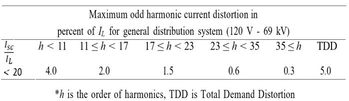
For systems rated at 69 kV and below, IEEE Std. 519 recommendsspecificlimitstoensurethequalityofpowerat the PCC. According to [9], it stipulates that the total harmonicdistortionshouldnotexceed5%,andindividual voltage distortion should be within 3%. Additionally, it provides guidelines for limiting the current distortion concerning the short circuit current (Isc) to load current ratio (IL), emphasizing the attenuation of higher-order harmonic components. To gauge the strength of the grid connection, [10] points out that the percentage of current ripplesintheinverteroutputcurrentisacrucialindicator. Forweakergridconnections,thestandardallowsfor0.3% current ripples, while in the case of stronger grid connections, this tolerance can be higher. This approach defines the smoothness of the output current, ensuring compliancewiththespecifiedgridconnectionconditions. The research work’s primary objective is to thoroughly investigatethedesignofaVSIanditsimpactonoperational performance,particularlyunderconditionsofaweakgrid, whilesimultaneouslyupholdingestablishedpowerquality standards.Inordertoattainthisgoal,itisimperativetogain a comprehensive understanding of how the inverter functionswithinadistributionnetwork.Aweakgridismore susceptible to voltage drops, harmonic distortion, and equipment failures. This is because the higher impedance can cause the voltage to drop more as the current flows throughthegrid.Itcanalsoamplifytheeffectsofharmonic distortion and make it more difficult for equipment to operate reliably. Also, weak grids can undermine sustainability by increasing energy losses, reducing reliability,increasingthecostofelectricity,andlimitingthe integrationofrenewableenergy.
International Research Journal of Engineering and Technology (IRJET) e-ISSN: 2395-0056
Volume: 11 Issue: 09 | Sep 2024 www.irjet.net p-ISSN: 2395-0072
thesecircumstances.This means thatwhena microgrid is
The stability of grid-connected inverters can be comprehensively assessed by examining their response to both small andlarge-scale disturbances within the control signal,asdiscussedin[11][12].Thesmall-scaledisturbances may not significantlydisrupt VSIsynchronization with the grid but can manifest their effects during grid feeding, potentially leading to the generation of harmonics and voltage instability at the PCC [13]. To evaluate instability arisingfromsmallsignals,twodistinctmethodshavebeen proposed:onebasedoneigenvaluesandtheotherbasedon impedance.Furthermore,insuchoperatingconditions,the interplaybetweenthePhaseLockedLoop(PLL)andCCLcan introduce current distortion, emerging as a key factor in potential system instability, as outlined by [11]. Effective dampingmechanismsplayapivotalroleinpreservingsystem equilibrium during transient network conditions. This research,therefore,conductsacomprehensiveexplorationof inverterstabilityissues,particularlywhenoperatinginweak gridscenariosandamidstdynamicconditions.
Traditionally, impedance-based system stability criteriahavesolelyreliedonnetworkimpedance,regardless of variations in the current reference [14]. In reality, the current reference can also affect the stability of a power system.Forexample,ifthecurrentismeasuredatapointon the grid where the impedance is high, then the system is morelikelytobecomeunstable.Therefore,theimpedancebasedstabilityapproacheshavebeenoutlined,including(a) designing control strategies that enhance adaptability to changes in grid impedance, (b) adjusting the output impedance of the VSI when it’s connected in parallel with other devices or passive components, and (c) considering impedancevariationsinfilterdesignandVSIcontrol,where parameters are determined based on grid-side impedance changestopreventinstabilityconditions[15],[16].However, it’simportanttonotethatinweakgridconditions,thegrid impedancecaninteractwiththeCCL,potentiallyleadingto system instability. This paper explores all three of these methodsinexperimentalscenarios.
Microgrid management strategies are designed to attainoptimalpowerschedulingthroughtheimplementation ofcontrolleractions.Twodistinctapproacheshavebeenput forth:theRule/Reference-basedapproachandthePredictive optimization-basedapproach.TheTunable-Rule/ReferenceBased-Heuristic(TRBH)approachoffersanotableadvantage byinherentlyfurnishingare-settingstrategy.Thisisachieved by computing a specific outcome based on a particular illustrationconformingtotheoptimaltuningdispatchrule. Consequently,predictiveoptimizationisnotrecommended astheprimarycontrollingmethod[17].
Ingrid-connectedmode,thegridisthedominantfactor,
1.1 Motivation anditisgenerallyassumedthattheoperationisstableunder
connected to the main grid, the main grid is the primary sourceofpowerandcontrol,anditistypicallyexpectedto beinastableandreliablestate.However,whenconfronted with weak gridscenarios,theprimary focusshiftstoward evaluatingthecontroller’sperformanceanditsadaptability toimpedancevariations.Forlowerandmedium-levelVSIs, improvementsintheinverterswitchcontrol,combinedwith well-designed filters, have proven advantageous in enhancingthequalityoftheoutputcurrent,discussedin[18] and[19].Nevertheless,theseenhancementsmayimpactthe controlbandwidthandthevariationingrid-sideimpedance. Toachievebetterperformanceandpowersupplyquality,it isimperativeforthecurrentcontrollooptoexhibithigher control band- width and swift dynamic response. Prior studies[20],[21],underscoretheimportanceofjudiciously selecting controller gain values based on filter design and power-sharingcriteria,necessitatingprecisespecificationof the control range. Controller parameters must be meticulously designed to minimize errors resulting from anticipated input values. However, the core concept of current regulation entails comparing reference and measuredoutputcurrentvalues,enablingerrorutilizationto modulate power electronic converters’ switching for the attainmentofdesiredoutput[22].
Throughout history, various methods have emerged to efficientlytunePID/PIcontrollers,particularlyforsystems with complex, inverse responses. These methods, like Ziegler-Nichols (1942) [23], Cohen-Coon (1953), and Tyreus-Luyben (1997), rely on inherent process characteristics and involve oscillatory approaches. While established, these methods are known for being timeconsumingandimpreciseduetotheirrelianceontrial-anderror.Incontrast,theInternalModelControl(IMC)method, introducedbyRivera(1986)[24],utilizesafitnessfunction todetermineoptimalcontrollerparametersdirectly,offering amoreefficientandaccuratesolution.
Within the realm of computational intelligence algorithms, including Artificial Neural Networks (ANN), GeneticAlgorithms(GA),ParticleSwarmOptimization(PSO), Predictive Model Control (MPC), and others, these techniques offer promising solutions for accurately determining controller gain values [25],[26]. PSO, in particular,hasgained widespreadacceptanceowingtoits simplicity, computational efficiency, and robustness, as it wasoriginallyintroducedbyKennedyandEberhartin1995 [27],[28].Overtime,througha trial-and-errorprocedure, variousalgorithmparametershavebeenrefinedforeaseof implementation across diverse applications, as seen in Eberhart,Simpson,andDobbins(1996).ThePSOalgorithm can accommodate different fitness functions tailored to specific objectives. For instance, the Integral of Time multiplied by Absolute Error (ITAE) performance index criteriaforcontrolsystemdesignwasintroducedbyGraham
International Research Journal of Engineering and Technology (IRJET) e-ISSN: 2395-0056
Volume: 11 Issue: 09 | Sep 2024 www.irjet.net p-ISSN: 2395-0072
Factors Real-coded GA
Representation
Search mechanism
Strengths
Weaknesses
Robustness to noise
Data types
Ability to solve multi-objective problems
Chromosomes(stringsofgenes)
Particles(positionandvelocity)
PSO
Particles(positionandvelocity)
Velocityandpositionupdatesbasedon individualandsociallearning
Globalsearch,goodatfindingdiversesolutions Fastconvergence,efficientforproblems withcontinuousdecisionvariables
Canbeslowtoconverge,pronetogettingstuck inlocaloptima
MorerobustnesstonoisethanPSO
Canbebinary,integer,orreal
Cansolvemulti-objectiveproblems
and Lathrop in 1953 [29]. The PSO algorithm’s implementationsharessimilaritieswithGeneticAlgorithms (GA),initializingwithapopulationofrandomsolutions[30]. Table1comparesreal-codedGAandPSO,andshowsthat real-codedGAarebettersuitedforimplementationinthis case,especiallyintermsofrepresentationandrobustnessto noise. Also, real coded based GA is a better suited for the problems with real variables. To ensure closed-loop performanceandsystemstability,theRouth-Hurwitz(R-H) criteria can be employed to define the boundaries of the search space based on the closed-loop characteristic equation [31]. Advanced Digital Signal Processors (DSPs) playavitalroleinreducingcontroldelaytimeandenhancing system responsiveness, thus bolstering overall system reliability. Additionally, Field Programmable Gate Array (FPGA) circuits and the Space Vector Pulse Width Modulation (SVPWM) technique prove valuable for addressingissueslikesignaldelay,dead-time,andmitigating outputcurrentharmonics[32].
Ensuring the stability and reliability of a distribution network requires the design of a robust VSI, with careful consideration of critical factors like grid impedance variationsandthemaintenanceofpowerquality.However, in situations where generation systems are situated in remoteareas,themedium-voltagetransmissionlinesmaybe extended,resultinginasignificantinductivegridimpedance [33].Highgridimpedancecharacterizeswhatiscommonly referred to as a weak grid. In accordance with IEEE Std. 1204-1997[34],agridistypicallydeemedweakwhenthe ShortCircuitRatio(SCR)islessthanthree.Weakgridsare often encountered in remote or rural areas that rely on lengthyfeederlinesfortheirpowersupply.
Canbesensitivetoparametersettings
LessrobusttonoisethanGA
Canbebinary,integer,orreal
Typicallyonlyusedtosolvesingleobjectiveproblems
Basedontheprecedingdiscussions,wehaveprepareda comprehensive comparison, as presented in Table 2. This tableisinstrumentalinhighlightingtheuniquecontributions ofthispaperbycontrastingitwithvariouspriorworksfrom the literature. It not only aids in gaining a fundamental comprehension of VSI component design and parameter selectionbutalsoprovidespracticalinsightsforreal-world validation.
A comprehensive discussion on VSI design and parameter selection for the lower voltage network level is presented here.Theprimaryfocusrevolvesaroundaddressingtwokey challenges:managingimpedancevariationsatthePCCand enhancingthetrackingperformanceoftheCCL.Regarding this,thepapershowsthevalidationandmaincontributions ofthisworkasfollows:
(i). The paper’s primary contribution is an improved controller for VSIs, enhancing dynamic response in low voltagenetworks,especiallyduringtransients.Itemphasizes theneedforcontrollerstabilitytopreventinstabilityinweak gridconditions.Thepaperalsointroducesamethodtoselect VSIfilterparameters,aimingtominimizestoredenergyin componentswhileimprovingTHDlevelsatthePCC.
(ii). The paper examines the robustness of the proposed singleloopcontrollerinregulatingtheVSI'sbehaviorunder diverseoperationalconditions.
(iii). Throughsimulationsonareal-timesimulator,Typhoon HIL,thestudyvalidatestheeffectivenessofoptimizedCCL parameters.Theseparametersareassessed under varying conditionssuchaschangesingrid-sideinductance,gridSCR, and abrupt load changes, both in a VSI-based system connected to a weak grid and in a standalone distributed network. This analysis serves to confirm the controller’s
International Research Journal of Engineering and Technology (IRJET) e-ISSN: 2395-0056
Volume: 11 Issue: 09 | Sep 2024 www.irjet.net p-ISSN: 2395-0072
tracking performance in real-time scenarios, ensuring its reliabilityandadaptabilityacrossdifferentconditions. (iv). The two methods are employed to enhance inverter stability: (a) changing the output impedance of the VSI by adjusting the grid-side inductance, and (b) optimizing the parametersforfilterdesignandVSIcontroller.
The paper additionally introduces the implementationofaProportional-Resonant(PR)con-troller intheproposedVSIapproach.Thisadditionaimstoenhance harmonicattenuationatthePCC,particularlyinthepresence ofweakgridconditions,withtheultimategoalofimproving theTHDlevel.
The paper presents a comprehensive analysis of plantmodel-basedtuningrulesandoutlinesvariousfactors
toconsiderforoptimizingthecurrentcontrollergainvalues ofVSItoaddressvaryingproductionratesanddifferentgrid scenarios. This flexibility enables the controller to be finetunedtospecificoperatingconditions,therebyenhancingits overallperformanceandadaptabilityinpracticalscenarios. Thispaperisdescribedinthefollowingsections: Section 2 details the system description, Section 3 describes filter designing and parameters selection, Section 4 elaborates controllermodeling;PSOalgorithmandrealcodedbasedGA implementation, and sensitivity/fitness function, Section 5 givesresultsanddiscussionofthedifferentscenarioanalysis, and Section 6 concludestheworkdoneinthepaper.
Items References
This paper
Standardsandregulations [1],[2],[3],[4],[9],[10][34] ✓
Differentmodelingmethods [18],[20],[35] SRFandSF
Filterdesigning [10],[36],[37],[38],[39] withminimumenergystorage
Differentcontroltechniques [21],[22],[17],[40].[41] VOCwithPIandPRcontrollers
Controllertuningtechniques [23],[24] ZN,PSOandGAimplementation
Optimizationtechniques [25],[26],[27],[28],[29],[30] heuristicapproach
Stabilityanalysis [31],[12],[42] ingridfollowingandformingmodes
Impedancebasedstability [33],[11],[13],[14],[16], ✓
Real-worldimplementation [32],[12], withconsiderationofdifferentconditions
-1:VSISysteminGFLmode
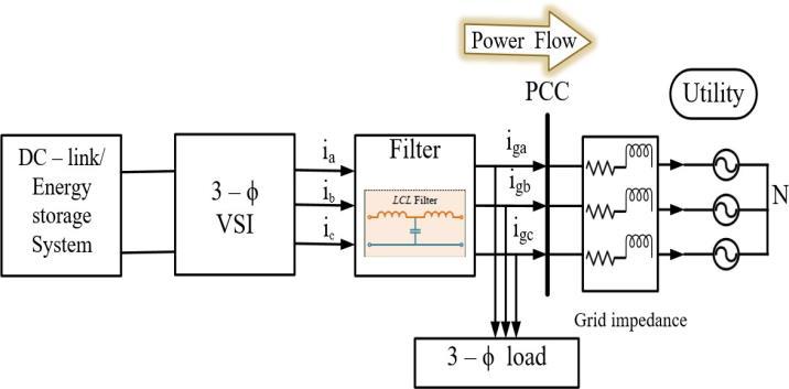
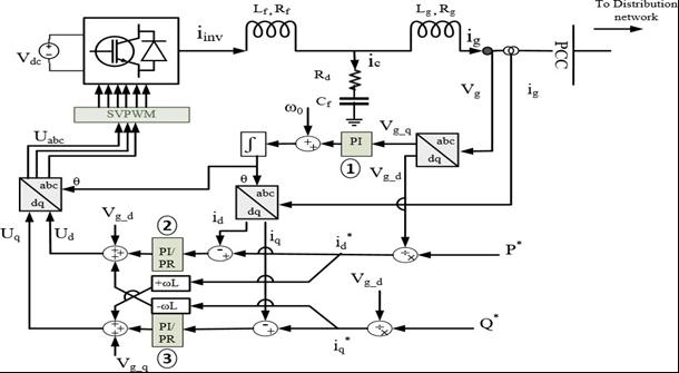
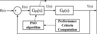
Inagrid-feedingmode,aVSI-basedsystemfunctionsasa controlledcurrentsource,asshowninFig.1,andplaysavital role in meeting power supply and demand requirements [18],[20].Moreover,thegrid-feeding(GFL)VSI-basedsystem injectsoutputcurrentwhilecloselytrackingthePCCvoltage. It also offers higher impedance to grid disturbances and noise, contributing to the overall enhancement of power quality within the system. Voltage-oriented control is the commonchoiceinVSI-basedsystemsforsynchronizationand control purposes [40]. Notably, power to the grid can be
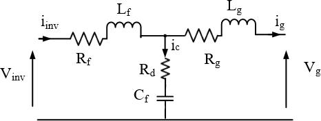
effectivelyregulatedbycontrollingtheoutputcurrentofthe VSI-basedsystem,especiallywhenthegridvoltageremains relativelyconstant.Fig.2illustratesagrid-connectedVSIwith anLCLfilter,taking3-ϕoutputvoltageandcurrentasinputs for the controllers. The switching signals for the VSI are generatedusingtheSVPWMscheme.
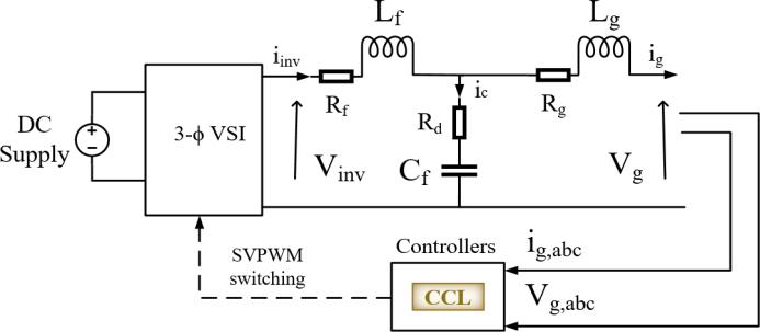
Fig -2:SchematicdiagramofgridconnectedVSIwithLCL filter
Theobjectiveofthecontrolleristoadequatelycontrolthe output current of the VSI by following the active power commandgivenbytheoperator.Asthecontrollerfollowsthe gridvoltageandinjectsthecurrenttothePCC,hence,power qualityissuespresentinthePCCvoltageworsenthepower
International Research Journal of Engineering and Technology (IRJET) e-ISSN: 2395-0056
Volume: 11 Issue: 09 | Sep 2024 www.irjet.net p-ISSN: 2395-0072
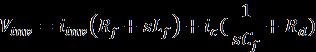
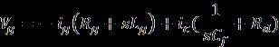
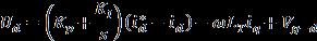
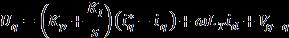
qualityoftheoutputcurrentoftheVSI.However,theoutput current’s power quality can also be improved by appropriatelydesigningthefiltercomponentsandthecontrol parameters. Here, the designing purpose parameters associatedwiththeVSIaretoimprovethesystemefficiency in terms of reliability, resiliency, and redundancy and the power delivered to the utility with improving the power quality.TheinverteroutputvoltageandcurrentfromFig.2 canbewrittenas,
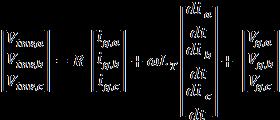

(1a) (1b) where Vinv{.} , iinv{.} , ig{.} , i{.} , ic{.} and Vg{.} represents inverter output voltage, inverter output current, grid feeding current, inductor current, capacitor current and the grid voltage of {a, b, c} phase respectively. The R = (Rf + Rg), and LT = (Lf + Lg) where Rf , Rg, Lf and Lg are the inverter side and grid side filter resistance and inductance respectively. Rd is a damping resistor. The Cf is the filter capacitance and ω is the grid frequency.
The filter acts as an intermediary between the VSI and PCC, enhancing the quality of the out- put current in compliancewith IEEE Std.519 guidelines. IEEE Std.519-2022 [43],alsoconcernedforharmoniccontrolinelectricpower systems,whichwasupdatedfrom IEEE Std.519-2014 [44]to includemorestringentharmoniclimitsatthePCCbetween the utility and the customer. This is necessary to accommodatetheincreasingnumberofnon-linearloadson the power system, such as variable frequency drives, and switch-modepowersupplies.Ingrid-connectedmode,the properselectionofthefilterandpower-sharingparameters ensuresthepower quality withintheregulated range and enhances the system performance against the transient conditions. The percentage of current ripple limits and harmonic distortions in output current recommendations are given in Table 3, which helps to design the filter componentsfortheVSI-basedsystem.
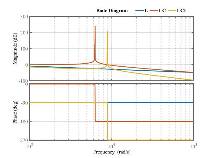
The higher switching frequency operation inverter applicationsavoidtheuseofonlyinductivecomponentsin thefilterforthemediumandhigherpowerratinginverters because of the bigger size requirement which turns into costlyandhighervoltagedropacrossit[36].Comparedto firstandsecond-orderfilters,thethird-orderLCLfilterhasa lower cost and is smaller in size which makes it more suitable for the inverter output connection with the main utility at medium and higher voltage levels. LCL filter provides excellent attenuation of bode 60 dB to the
switching frequency Fig. 3. But, in case the grid side impedanceislower,resonancecanbetriggered,leadingto systeminstability[10].Moreover,thisresonanceeffectcan subsequently cause voltage and current instability in proximity to the resonance frequency. The purpose of applyingtheresistivedamperistoreducetheattenuation andincreasethedamping(Q - factor)atthecharacteristic resonancefrequencywiththeminimumpowerloss.
TABLE-3: CURRENT HARMONIC LIMITS IN THE PERCENTAGE OF RATED CURRENT AMPLITUDE ACCORDINGTOIEEE519.
In summary, the design of the LCL filter concerns the followingpoints;
• Overallfiltersize,cost,losses
• Currentdistortionindifferentcomponents
• Resonanceanddynamicperformanceoftheoverallsystem
• Lowvoltagedropsacrossthefilter
• Higherpowerfactor.
Theparameterselection,accordingtotherecommended maximumcurrentdistortionlimitintheoutputcurrentset the percentage of current ripples in the inverter output currentistheprimaryconcerntodescribethelowerlimitof thefilterinductancevalue.Similarly,thefiltercapacitanceis chosen based on the energy stored in the capacitor. The selectionforthefiltercapacitorisa trade-offbetweenthe energy stored in the capacitor and the inverter-side inductance(Lf )[39].Thehighervaluecapacitanceusesmore reactive power to flow into the capacitor and more load currentdemandfromthe Lf andtheinverterswitches.Asa consequence, the system efficiency will be decreased. The
International Research Journal of Engineering and Technology (IRJET) e-ISSN: 2395-0056
Volume: 11 Issue: 09 | Sep 2024 www.irjet.net p-ISSN: 2395-0072
filterinductivereactanceshouldbelowerthanthecapacitive reactance,sothelowerthevoltagedropacross Lf .Generally, thereactivepowerforthecapacitorischosenbetween515%oftheratedcapacityaspertherequirement.
(a)
(b)
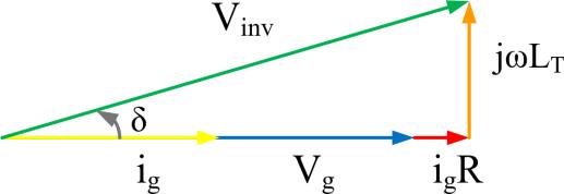
Fig - 3: (a).EquivalentcircuitdiagramofLCLfilter connectedbetweenVSIandgrid,(b).Phasordiagramfor theunitypowercondition.
The following equations represent the circuit shown in Figure 4(a)and(b).These equations will be employed to computethetransferfunctionoftheLCLfilter:

where, Vinv is the inverter output 3 − ϕ voltage vector, S represents the switching space vector, Vdc is the DC - link voltage, ic isthecapacitorcurrent, iinv and ig aretheinvertersideandgrid-sidecurrents.
(4)
Generally,theinitialoperatingconditionsofVSIshould be determined before selecting the filter parameters, like rated power (Prated), rated iinv, output voltage Vinv, inverter switching frequency, fsw, fundamental frequency, f0. The stepsforchoosingtheLCLfilterparametersareasfollows:
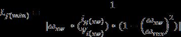
Step 1. Determinethemaximumvaluefortheinverter-side inductance, Lf, based on the maximum value of current ripples in the output current as follows: (5)

whereVdc istheinputDCvoltage,thatcanobtainfrom (2√3V(g,rms)/M)hereMisthemodulationindex,Disthe dutycycle, ∆i|max ismaximumcurrentripple,thatis generallysettobe20-30%.Asgivenin[10],tocalculate theminimuminductancevaluebasedonswitching frequencyisgivenas;
(6)
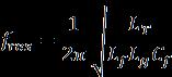
Step 2. Asdiscussedearlier,determinethefiltercapacitor valuebasedonthemaximumreactivepowerstoredinthe capacitorasgivenbelow;

where Prated istheVSIpowerrating, ω0 isfundamental angularfrequency.
(7)
Step 3. Based on selection of switching frequency, fsw, determinethefiltercut-offfrequencyas(1/10th)of(fsw)
Step 4. Determinetheminimuminductancevalueatselected fsw accordingtotheIEEEstd.asdefinedintableIIcurrent distortionandharmoniclimits,asgivenin(6).
Step 5. The maximum and minimum value of inductance providesaselectionrangefortheinverter-sideandgrid-side inductorstochoosethesuitablevaluesbasedonharmonic attenuationandtheinductanceratio aL (i.e., aL =Lf/Lg).The resonancefrequencydecreasesasthegrid-sideinductance increaseswithrespecttotheinverterside.Theratio aL =1, i.e., Lf = Lg, corresponds to the minimum capacitance requirementandlowerharmonicattenuation[10].
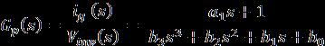
The transfer function of the LCL filter network Gp(s) is consideredasaplantforthecontrollersandcalculatedfrom theratioofoutputgridcurrent ig(s)totheinverteroutput voltage Vinv.(s)isrepresentedin(3); (3)
where, a1 = RdCf , b3 = Lf LgCf , b2
b3, b2, b1arethegrid-sideinductancedependentcoefficients,which affectthegridconnection(stiff/weakgrid)requirements.
TheresonancefrequencyofLCLfilteriscalculatedbyusing (4);
Step 6. TheTHDleveloftheoutputcurrentmustbebelow 5%.IfTHDishigherthan5%thendecreasetheattenuation rateanddesignthenewfilterparameters.
Generally, the filter parameters selection includes filteringandcontrollingissues,whichisatrade-offbetween better filter action (minimum current distortion) and fast dynamicperformance.Selectedfilterparametersaregivenin the Table 5. The trade-off is shown in the result, Section 5.1.1, and minimum current distortion, means better trackingofthereferencevalue.
International Research Journal of Engineering and Technology (IRJET) e-ISSN: 2395-0056
Volume: 11 Issue: 09 | Sep 2024 www.irjet.net p-ISSN: 2395-0072
Insituationswhereaweakgridconnectionexists,thereis ariskthatthecontrollersmaystruggletoaccuratelyfollow thegrid’svoltageorangleasareference,potentiallyleading toinstabilityinthesystem.Tomitigatethis,it’sessentialto configure the gain values within the CCL according to the characteristicsoftheplantmodeltoensureprecisetracking performance. Consequently, in order to optimize the performanceofLocalControlUnits(LCUs),itisimperativeto meticulouslydesignandfine-tunethecontrolparameters.
Thisisespeciallycriticalformaintainingsystemstability acrossawidespectrumofoperatingconditions,particularly inlowvoltagedistributednetworks[12].
The adaptive control scheme is built upon a cascaded feed-forwardcontrolstructure,featuringtwocontrolloops, theinnerandouterloops,operatingintheSynchronously RotatingFrame(SRF)andtheStationaryFrame(SF).Inthis context,theprimaryfocusofcontrollermodelingisonthe inner loop, which is meticulously designed to minimize settling times during power regulation and to enhance system dynamic performance. It is important to highlight that a single-loop control scheme while offering a compromise between fast control dynamics and stable steady-stateperformance,istypicallylessrobustduetoits sensitivitytogridnoise(suchasharmonics,voltagesags,or transients)[41].However,it’sessentialtoacknowledgethe interdependencebetweenactiveandreactivepowers,and theexistenceoffiltersandsourceinductancecanleadtothe occurrenceofanon-unitypowerfactorcurrent.This,inturn, introducesacross-couplingtermlinkingthed-axisandq-
axiswithintheSRF,whichcanhaveadetrimentaleffecton controllerperformanceandpowerregulation.
In the context of GCI systems, employing decoupling techniques is essential for mitigating sensitivity to load changes,enhancingdisturbancerejectioncapabilities,and reducingtheoutputcurrentTHD,particularlywhendealing withnon-linearloads.It’sevidentthatthecontrollerplaysa pivotalroleinshapingthequalityofthecurrentsuppliedto the primary utility, ensuring a sinusoidal output with minimalTHD.
ThemostwidelyusedPIandPRcontrollersareconsidered controllersfortheinverteroutputcurrentregulation.The relationship given for the system in equation 1(a), is convertedintothesynchronousframeas;
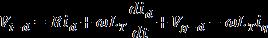
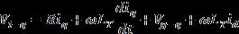
Fromtheabove equations,theactiveandreactivepowers canbecalculatedas:


The current injected into the grid is expected to be in phasewithgridvoltagewhichmakestheoperationatunity powerfactor.Therefore, Vq = 0,ineq.(9a)and(9b),weget; Pi =1.5 Vdid and Qi =-1.5Vdiq,whichprovidesdecouplingfor thebettercontrollingbetweentheactiveandreactivepower flowtothegrid.
The adaptive current control scheme is deliberately designedwithrelativelylowercomplexitytoaccommodate thechallengesposedbyvaryingsystemparameters.Inthis
International Research Journal of Engineering and Technology (IRJET) e-ISSN: 2395-0056
Volume: 11 Issue: 09 | Sep 2024 www.irjet.net p-ISSN: 2395-0072
approach, the grid-side voltage (Vg) and current (ig) variables serve as key input parameters for the CCL. The direct axis current (id) component is computed using the measuredoutputcurrent,andthenecessaryphaseanglefor thisconversionisgeneratedbythePLL.Theidcomponentis then compared with the reference value id * to generate modulatingvoltagesignalsasperequations(10a),(10b).
FromFig.5,theoperationofthecurrentcontrollerinSRF canbeexpressedas:
(10a) (10b)
where KP istheproportionaland KI istheintegralgain valuesofthePIcontroller.
ThePIcontrollerin dq frameexhibitsasinglepoleatzero frequency,resultingininfinitegain.However,itisincapable of eliminating steady-state error at the fundamental frequency. In a positive sequence SRF, the PI controller behavior is equivalent to the PR controller in SF [21]. Alternatively,thePRcontrollerin αβ frameisadvantageous duetoitshighgainattheresonantfrequency.AspertheIMC principle, it can eliminate the steady state error while trackingthesinusoidalsignalandprovidesbetterharmonic attenuation. The additional damping factor in the ideal resonant term makes the PR controller more reliable for practicalapplicationsandcanberepresentedasexpressed in(11);

(11)
where ω0 is system fundamental angular frequency, ωc is cut-offfrequency, ξ isdampingfactor.
To maintain the robustness of the PR controller, the ωc bandwidthmustbecloseenoughtothesystemfrequency.If the system frequency varies significantly, the ωc can be adjusted accordingly. Therefore, in comparison to PI controller,thePRcontrollerhasanadvantageinclosed-loop performanceforfrequencyvariations.
As depicted in Fig. 5, it’s evident that the reference voltage and current are derived from the PCC. These reference signals can be distorted due to the weak grid conditions. This distortion has an impact on the CCL performance, which needs to be enhanced to improve the overall performance of the VSI. When using a single-loop control system in the presence of grid noise, such as fluctuations or disturbances in the electrical grid, the stabilityoftheVSIiscompromised.Gridnoisemayintroduce unpredictablevariationsintheelectricalparametersthatthe control system relies on, leading to instability in the VSI's operation. As a result, the effectiveness of the single-loop controlsysteminregulatingtheVSI'sbehaviorislimitedor constrained. Determining the appropriate controller gain values is critical in control system design. It ensures the systemstabilitywhileachievingthedesiredleveloftracking
performance and meeting the safety and performance requirements.Thecontrollertuningpurposeistominimize the overshoot and time response for transient conditions. When the parametric uncertainty and performance specifications are fixed, controller parameters can be optimizedforanypossiblecase.
To enhance the stability of a VSI, the controller gain values, filter parameters, and power- sharing parameters mustbekeptwithintheprescribedlimits.Theoptimization of controller parameters is synthesized with the offline procedure, ensuring the operating range of the other components.Theperformanceindexis basedonerror(e) minimization and used for further optimization implementationasgiveninthefollowingequation;

s.t., KP max >KP > KP min , KI max >KI> KI min
Where, KP max and KP min are the maximum and minimum valuesoftheproportionalgainand KI max and KI min arethe maximumandminimumvaluesoftheintegralgainofthePI controller.
TheITAEperformanceindexcriteriatodesignacontrol system is derived by using a set of 2nd- order to 8th-order normalized transfer function coefficients to minimize the ITAEindexcriteriaforastepsignal[29].Sinceitcanprovide highdisturbancerejectioncapabilitytothecontrollersand minimizetheovershootduringtransients.Thisindexisalso oftenusedforsmalldatasetsordataobtainedfromthestep response.ITAEperformanceindextrades-offbetweenerror magnitudeandsettlingtime[45].Inthispaper,thefitness functionforthecontrollertuningisbasedonminimizingthe ITAE,whichiscalculatedbyusingSimpson’s1/3rule.The expressionfortheITAEperformanceindexisgivenby(13);

(13)
where, t is the time and e(t) is the error produced by the differencebetweenreferenceandmeasuredvalue.
PSOisaniterativemethodthatdependsontheproblem searching space to determine the optimal solution for the fitnessfunctionshowninFig.6.Thisalgorithmisevaluated based on the movement of each particle and the swarm experience. Each particle movement is based on its own experience and collaboration of the swarm. It attracts towardsthebestlocalposition(X(p,best))experiencedbyits own and best global position (X(g,best)) by the swarm. The basicrulesofthePSOalgorithmcanbebrieflydescribedin thefollowingstages;(a).Findingoutthefitnessvalueofeach
International Research Journal of Engineering and Technology (IRJET) e-ISSN: 2395-0056
Volume: 11 Issue: 09 | Sep 2024 www.irjet.net p-ISSN: 2395-0072
particle,(b).Updatingthebestlocalandglobalpositions,(c). Updatingvelocityandbestglobalposition.
Mathematically,thesearchprocesscanberepresentedby the simple equations with concerning position vector Xi = (xi1, xi2, . . . , xin)andvelocityvector Vi =(vi1, vi2, . . . , vin)within thespecifiedselectionrange.Theoptimalityofthesolution depends on each particle’s velocity and position which is updatedasequation14inthealgorithm.

where, i represents the index of the particle; Xik and Vik defined as the position and velocity of the particle i at kth iteration,respectively; w representstheinertiaweightwhich cansetbetween[0-1](asmallinertiaweighthelpsinexplore the search space while a large inertia weight facilitates in exploit the search space), and also provides the balance between local and global explorations and exploitations which results in fewer iterations on average to find a sufficientlyoptimalsolution; c1 and c2 aretheacceleration constantsusedtoguidetheparticle’smovementtothe pbest and gbest positions; r1and r2aretherandomnumbervariable between[0-1].
Boundedsearchingspaceprovidesfastsolutions,butin case the optimum global value is located outside of the boundary conditions, it influences the optimality of the solution [25]. However, the boundary conditions can be extended butthiswouldincreasethecalculationtimeand can affect the optimal solution. Therefore, sufficient informationaboutthesystemparameterslimitisbeneficial tosettheboundaryconditionsforthesearch.
The implementation of GA is the same as the PSO algorithmandasearchmechanismtofindouttheoptimal solutionfromthegivenproblems,whichisinherentlybased onitsnaturalselection.GAprovidesasolutionbasedonthe chromosomes that can adapt to the change in the surrounding environmental conditions and are able to reproduce crossover and mutation. In other words, GA simulation is based on the “survival of the fittest” among individual steps of consecutive generations for solving a problem.So,thesolutionforeachsuccessivegenerationis moreadaptablefortheirsearchspace.Thesimulatedbinary
crossover (SBX) operator uses a parameter (known as distributionindex, ηc)tomaintainthepositiveintegervalue during the overall running time of the simulation. This parameterhasadirecteffectoncontrollingofgenerationof offspringsolutions[46].Thegenerationofoffspring and fromtheparent and isdefinedas;


(15)
where, βi is called as the spread factor. The probability distribution index (ηc) plays a crucial role in single-point crossover (SPX) by influencing the "search power" of the offspringsolution.Theprobabilitydistributionindexallows to control the “spread”, which affects the diversity of offspringsolutionsaroundtheparents.Highervaluesof ηc (closer to 20) lead to offspring with values closer to the parent's average, limiting exploration. Lower values of ηc (closer to 2) generate offspring with values further away fromtheaverage,encouragingexploration.Theprobability distributionindexisusedtocreateanoffspringwithsimilar search power in single point crossover, which can be representedasin(16); (16)

By using the random number and the probability distributionfunction,helpstoselectanewvalue“βqi”fora specific characteristic of the offspring in the evolutionary algorithm. This value is chosen in a way that reflects the desired distribution of characteristics in the population, guidingthealgorithmtowardspromisingsolutions.Froma definedprobabilitydistributionindex,theordinate“βqi”is foundwhichishelpfulfortheoffspringgenerationasgiven inthefollowingeqns.;
(17a) (17b)
Crossover is performed with a higher probability (Pc), whereasthemutationisperformedwithalowprobability (Pm),seeTable5.Ifthemutationprobabilityiskeptverylow, then no element would be mutated by the mutation operator.
Generally,whenthefitnessfunctionisprovidedtoGA,itis used to observe the behavior of the function in the given criterionoftheproblem.So,inthecaseoftheminimization of objective function value, the lowest value would be the mostsuitablesolutionforthegivensituation.Thedeveloped algorithmisproposedtofindouttheoptimalcontrollergain valuesbasedontheminimumerror.
The finally designed VSI components’ parameters are tested under dynamic operating conditions in standalone mode for stability analysis. In standalone mode, three VSI sources are considered to create an isolated microgrid environmentwithcriticalandnon-criticalloads,asshownin Fig.7.Themainpurposeofthisstandalonenetworksystem
International Research Journal of Engineering and Technology (IRJET) e-ISSN: 2395-0056
Volume: 11 Issue: 09 | Sep 2024 www.irjet.net p-ISSN: 2395-0072
istoevaluatethestabilityandperformanceofthedesigned VSI in terms of frequency and voltage stability during the transientcondition.Itiscrucialtoinvestigateanypotential disturbanceinmicrogrids,particularlyintheislandedmode, because the inertia is low. When operating in the droop control mode, the bus frequency and voltage amplitude reflect, respectively, the output active and reactive power that satisfies the P-f and Q-V droop characteristics. The droopcharacteristicequationscanbeexpressedas; (18a) (18b)
where,mandnarethedroopcoefficients, fref and V ref arethe busfrequencyandvoltageamplitudeatthePCCand Pref and Qref aretheactiveandreactivepoweroftheDGunits.

TheproposedGCIsystempowerratingis10kWwith3Φinductive load, as shown in Fig. 1, which is designed and testedinMATLAB/SIMULINKwithm-files.TheSIMULINK block diagram is given in Fig. 5. This paper validates the designedLCLfilterforharmonicattenuationandverifiesthe stabilityconditionsofthecontrollerusingtheTYPHOONHIL
emulatorforreal-timeperformance.Thecontroller’sdesign is primarily oriented towards enhancing tracking performance,especiallyinsituationscharacterizedbyaless stablegrid.
TABLE - 5: SELECTEDPARAMETERSFORTHE EXPERIMENTALSET-UP
bound(KP min, KImin)
Thepolesandzerosofthedesignedfilterareintheleft halfofthes-plane,whichrepresentsthefilterstability.By additional damping in the filter, the system stability is enhanced,showninFig8(a).Asweincreasetheswitching frequency,thefilterbecomesmoreeffectiveateliminating higher-order harmonics. To evaluate stability comprehensively, we have analyzed the gain and phase marginsthroughtheplant’stransferfunctionandBodeplots, depicted in Fig. 8 (b). This analysis provides valuable insightsintothefilter’sstabilityanditsabilitytosuppress harmonics,essentialforassessingitsperformance.
International Research Journal of Engineering and Technology (IRJET) e-ISSN: 2395-0056
Volume: 11 Issue: 09 | Sep 2024 www.irjet.net p-ISSN: 2395-0072
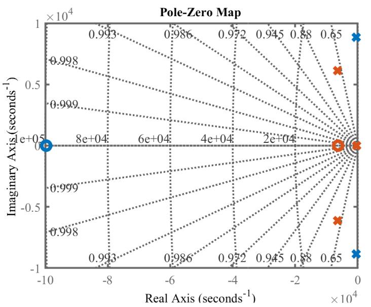
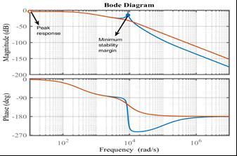
(b)
Fig - 8: Stabilityanalysis(a). Poleandzerosoftheclosed loopsystemwith(red)andwithout(blue)damping, (b). Bodeplotoftheplanttransferfunctionwith(red)and without(blue)damping
A higher switching frequency (refer to Table 5) is employedthroughoutthesimulation.Thishigherfrequency assists in the precise tracking of time-varying signals, compensatingfordeadtime,andreducingcurrentripplesin theoutputcurrent.
Thesimulationparametersusedforthesystemdesignare giveninTable5.
Table - 6: COMPARISONOFCONTROLLERGAINVALUES ANDSTEADY-STATERESPONSEWITHDIFFERENT CONTROLLERTUNINGTECHNIQUES
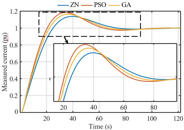
- 9: PIcontrollergainresponsecomparisonwithZN, PSOandGA
Theselectedcontrollerparametersaredetailedinboth Table5andTable6.Toinitiatetheoptimizationprocesses, theinitialparametersforthePSOandGAarederivedfrom theZNmethod,whichassistsinestablishingtheupperand lower limits. In Fig. 9, a comparative analysis of the PI controller’ssettlingtime(Tss)andmaximumpeakovershoot (Mp)isconductedacrossdifferenttuningmethods,including ZN,PSO,andGA,andtheresultsaresummarizedinTable6. Notably,GAoutperformstheothermethodsbyachieving Mp value and Tss that aligns with the desired criteria. Consequently,theGAtuningmethodisselectedforfurther experimentalvalidation,asitmeetsallthespecifiedcriteria. The exploration into the controller’s performance under weakgridconditionsispromptedbytheintermittentnature ofrenewablesourcesandvariationsinload-sideimpedance. Inthiscontext,the figures,specificallyFig.10,11,and12, illustrate the dynamic response of the PI controller under variousconditionsduringpowerregulation.Thesefigures underscore the controller’s efficacy in the nonlinear time domain,particularlywhentherearechangesincurrentfrom 15A to 20A, demonstrating its dynamic response and its capabilitytocontrolreactivepowereffectively.
The experiment aims to verify the obtained controllerparametersfromreal-codedbasedGA,seeTable 6,withthePIandPRcontrollers’performanceforweakgrid operating conditions based on Lg variation and (X/R) variation, fault occurrence at the PCC and also tested for suddenloadchangeinthestandalonedistributednetwork.
5.1.1 Effects due to Lg variations
In general, Lg is kept lower than Lf as suggested in many works of literature [36],[37]. Therefore, here the CCL performanceistestedforthelower Lg valuestoachievethe consideredobjectiveforthedesignedfilter.Thecontroller performance is responsible for controlling the active and reactivepowersupplytotheutility,asshowninFig.10(a)
International Research Journal of Engineering and Technology (IRJET) e-ISSN: 2395-0056
Volume: 11 Issue: 09 | Sep 2024 www.irjet.net p-ISSN: 2395-0072
and(b).Thefigureimpliesthatthecontrollerachievesthe steadystatewithinthestandardtime(Tss =3-5ms)and Mp within 5% for the CCL. We find the Lg variation for the transientconditioninCCL,whichcouldberesponsiblefor the system’s stability. The minimum Lg value has the maximum Mp and Tss. The best controller tracking performanceisobtainedwhen Lg issetto2.53mH,the Mp and Tss arewithinthedesiredcriteria,seeinFig.10(a).At thisvalue,theinductanceratio(aL)wouldbeone,andthe capacitor requires minimum energy storage, which also fulfills our filter design objective. From the above demonstration it is clear that as the controller performs worse as the Lg value decreases, so it is important to maintain the grid impedance according to the connection requirements.Inweakgridscenarios,itisbettertoconsider equalizingthevalueofLf toreduceharmonicsandcurrent distortionattheloadside.
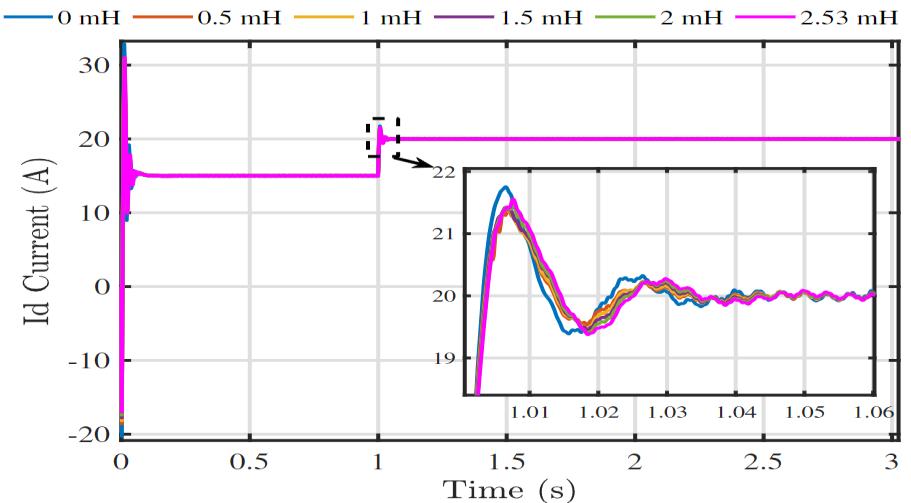
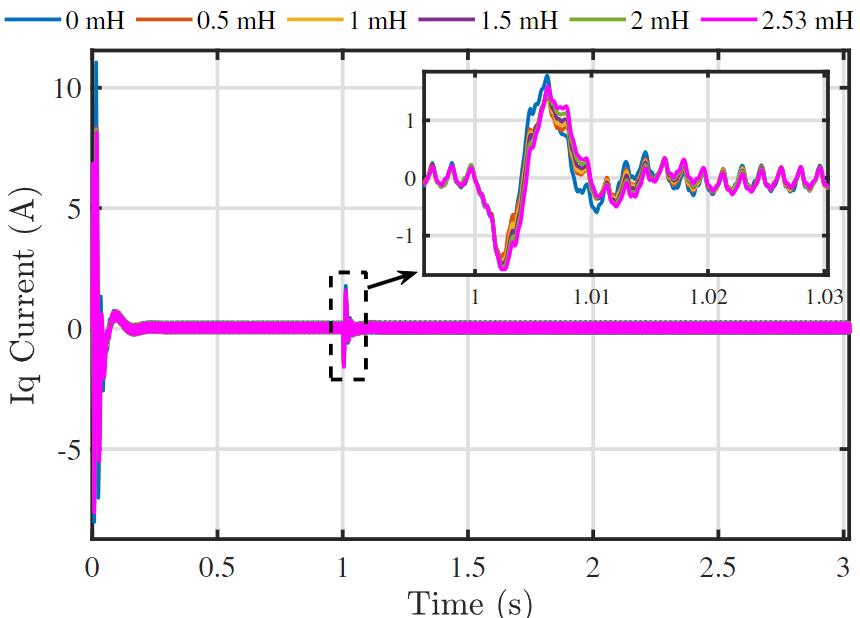
Fig - 10: (a).ComparisonofId currentwithLg variation, (b).ComparisonofIq currentwithLg variation.
5.1.2 Effect on (X/R) variation
Tostudydynamicconditions,twotypesofdisturbancesare considered;asuddenchangeinpowerdemandandachange
inthelineimpedance.Inalowvoltagedistributionnetwork, thelowerlineimpedanceatthegridside,incaseofsudden load changes, creates a severe problem that affects the controller performance and overall system efficiency (especiallylowerSCRvaluesystemsduetoover-current).In Fig.11(a)and(b),thecurrentissteppedupat0.5seconds toincreasethepowersupply.Theweakgridcharacteristics aredefinedas,SCR<3and(X/R)<5[11].WhereTheSCR specifies the maximum amount of power that the power systemcanhandlewithoutcompromisingpowerqualityat the PCC. As shown in Fig. 11 (a), the controller is quite robusttoavoidtheinstabilityconditioninthesystemand track the reference value with minimum oscillations. The bestcontrollertrackingperformancewithminimumripple current (based on Tss, Mp) is achieved when the (X/R) is equalto2.5,whichiswithinweakgridconditionatthegridside.
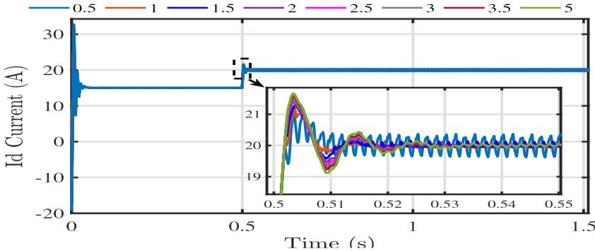
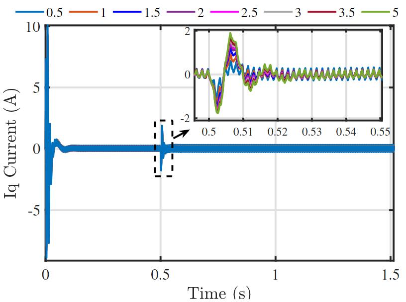
Fig - 11: (a).ComparisonofId currentwith(X/R) variation,(b).ComparisonofIq currentwith(X/R) variation.
5.1.3 Effect of fault occurrence at PCC
Generally,athree-phasefaultisconsideredforthecontroller performance and the system withstands capacity for the short circuit current analysis during transient conditions. Becausethemaximumfaultcurrentoccursin3-phasefault.
International Research Journal of Engineering and Technology (IRJET) e-ISSN: 2395-0056
Volume: 11 Issue: 09 | Sep 2024 www.irjet.net p-ISSN: 2395-0072
Whenanyfaultoccurs,theprotectionrelayoperatingtimeis about0.22seconds[11].TheCriticalClearingTime(CCT)is atypicalcriterionforevaluatingthetransientstabilitylimits. AswecanseeinFig.12,thefaultisclearedwithinCCT,and thecurrentsignalisbackonthetracksetbythecontroller. The controller limits the fault current during the fault conditionanddoesnotallowittoexceedthedesiredvalue.It shows the robustness of the controller and fault ridethroughcapabilityforlowerstrengthsystemstorecoverthe voltagestabilityafterthefault.
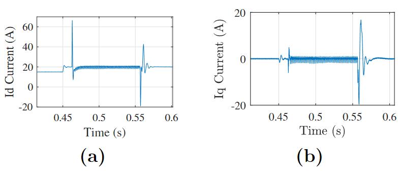
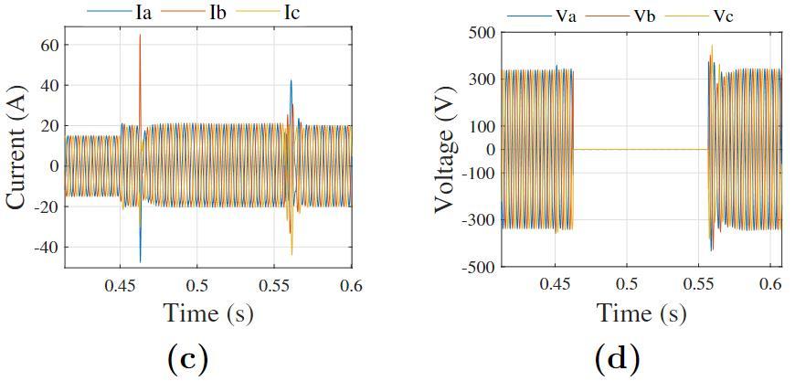
Fig -12: (a).Id current,(b).Iq current,(c).VSIoutput3ϕcurrentduringthefaultcondition,(d).Output3ϕ-voltage duringthefaultcondition.
PIcontrolleroperatesonafixedfrequencyofthesystem,so itsoutputcouldbeunstableunderweakgridconditions.But the PR controller has cut-off frequency bandwidth (ωc) around the system frequency, as discussed earlier in the current controller structure. For this experiment, the frequencyvariationisconsidered±2Hz.Theparametersare determined similarly to the PI controller to obtain the requiredclosed-loopresponsefromthePRcontroller.The cut-offfrequencybandwidthcanbeextendedbytuningthe ωc.Thehighervalueofωc isresponsiblefortheincreasein peakmagnitudeatthesystemfrequency,whichcorresponds toahighergainvalueandbettercurrentrippleattenuation. Thelowervalueofωccorrespondstowiderbandwidthatthe systemfrequency[47].ThecomparisonforTHDanalysisby usingPIandPRcontrolleris showninFig.13.Theoutput currentTHDlevelsare below 3%asperrequirementsfor theweakgridapplications,whichshowsthequalityofthe outputcurrent.
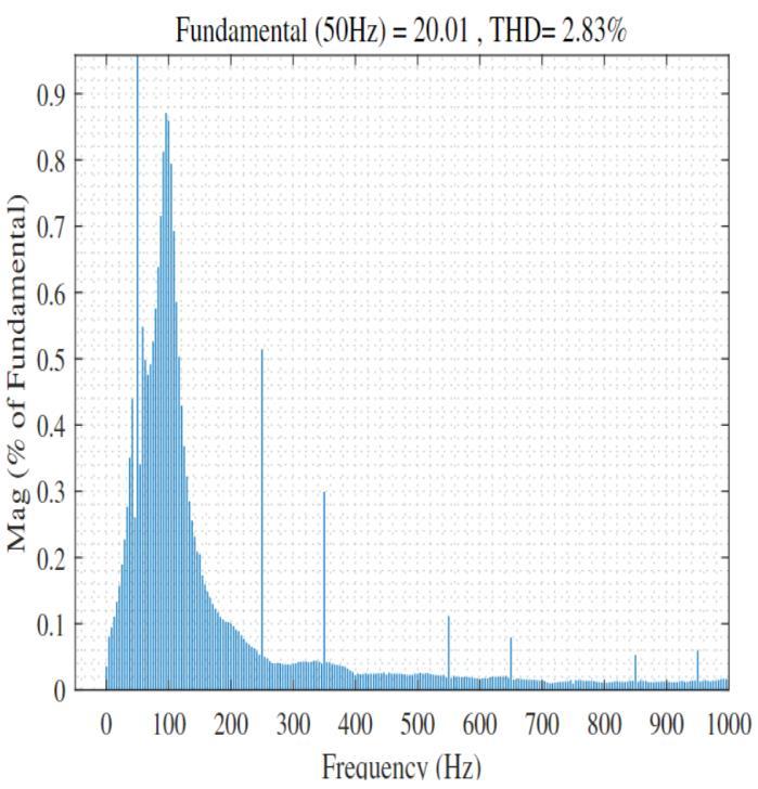
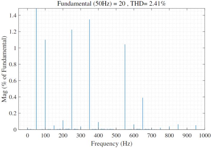
Fig - 13:THDanalysisofVSIoutputcurrent(a).forPI controller,(b).forPRcontroller.
5.1.5
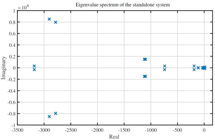
In Fig. 7, the designed three VSIs (10kVA each) are connectedtoadistributednetworkinstandalonemodefor testing the stability and reliability performance. The eigenvalue spectrum of the consider network in Fig. 14 demonstrates the effectiveness of the designed controller system.Thenegativeeigenvalues indicatethatthesystem remainsstable duringstandaloneoperation. Thedifferent clusterpositionsshowthedifferentmodesinthemicrogrid system,suchasdistributionline,filter,power,voltage,and currentcontrollerstatevariables.Fig.15demonstratesthe effectivenessofthecontrollertrackingperformancewhen thereisasudden20%increaseinload-1atDG-1.Thesmall loadvariationataparticularDGinthenetwork,whilehere theloadincreaseoccursat0.5seconds,leadingtochangesin
active power sharing and consequently affecting the VSI frequency shown in the figure. However, active power oscillationsmayoccurbetweenparallelinvertersduringthe
International Research Journal of Engineering and Technology (IRJET) e-ISSN: 2395-0056
Volume: 11 Issue: 09 | Sep 2024 www.irjet.net p-ISSN: 2395-0072


- 15: StabilityanalysisofthethreeVSIstandalonesystemwhensuddenloadincreasedat0.5sec. loadfluctuations,butherethepowerflowissmoothwithout usinganyexternaldampingtechniques.
5.1.6
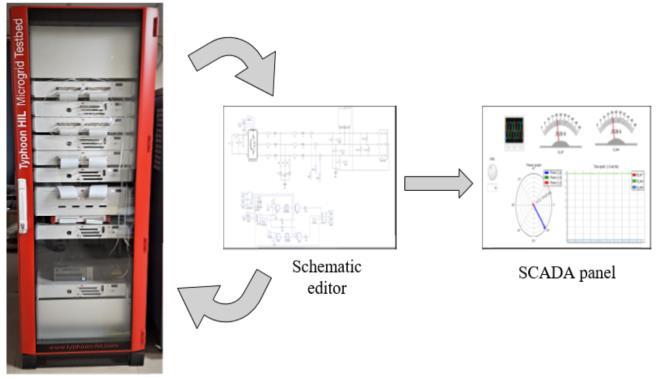
The plant function, considering all aspects outlined in sectionIII,andtesteditinMATLAB/SIMULINK.Thistesting helps us select accurate parameters in line with standard requirements[4],[9].Thecontrollergainvalueshavebeen diligently calculated using three distinct methods to optimize controller performance during operation. These optimizationalgorithmshavebeenimplementedincustom m-files.Theeffectivenessofthecontrollerloopoptimization hasbeenrigorouslytestedandverifiedusingtheTyphoon real-time emulator model-604, which provides an impressive 20-nsec sampling resolution. In Fig. 16, the schematiceditorisusedforVSImodelingpurposes,whichis compiledwiththereal-timehardwareemulatorset-up,and theSCADA(SupervisoryControlandDataAcquisition)panel isusedformonitoringandvisualizationoftheoutputresults.
The Typhoon set-up is connected through the Ethernet connectionmodetothedesktopsystem.Thevalidationon Hardware-In-Loopimplementationiscompletelyreliablefor thecoordinatedpowerfeedingtotheutilityfromdifferent power generation sources through the connected power converter.
5.1.7 Discussion
Accordingtothefindingsin[9],theparameteroptimization hasyieldedsatisfactoryresults,astheTHDleveloftheVSI output current remains consistently below 3%. In direct comparisontotheresultspresentedin[19],itisevidentthat thefilterandcontrollerparameters,aswellastheresulting THDlevels,areimprovedandbetterthanthegivenresultsin thementionedpaperforthesameinverterrating.Moreover, weak grid stability issues discussed in references such as [14]and[15]havebeensuccessfullyaddressedthroughthe application of universal control modeling and various operating conditions tailored to weak grid scenarios. To mitigate the impact of grid- side impedance variations on
International Research Journal of Engineering and Technology (IRJET) e-ISSN: 2395-0056
CCL,thisstudyhassystematicallytesteddifferentcontroller tuningmethods,meticulouslydocumentedinTable6.The stability of the impedance variation-based controller performanceisdemonstratedinFig.10and11.Thestudy’s rigor extends to testing the VSI’s performance during a three-phasefaultoccurrenceatthePCC,asillustratedinFig. 12.Furthermore,theVSI’sperformancewasassessedin a standalone distributed network subjected to sudden load changes,revealingitsrobustcontrollertrackingcapabilities inparalleloperation,whichisvividlydepictedinFig.15.The results collectively demonstrate that the designed VSI parametersareversatileandadeptathandlingaspectrumof scenarios, particularly in less stable conditions. The ComprehensiveCCLtrackingperformanceunderscoresthe VSI’sreliabilityeveninchallengingreal-timeconditions.
6. CONCLUSION
Inthispaperthegridimpedance-basedstabilityisconcerned and improve the inverter stability for lower-voltage distribution networks. The calculated filter and controller parameters show their best performance for weak grid conditions. The GA results are the best option for the controllerconsiderationsforcontrollerperformance.Finally, itinvestigatesthedesignedsystemparametersforcontroller trackingperformance.ThevariationsinLgand(X/R)shows the impact on controller performance during grid-side impedancevariations.Thecontrollertrackingperformance is satisfactory for weak grid impedance scenarios. The performance at fault occurrence and sudden load change conditionsshowstherobustnessofthesystem.Toimprove theTHDlevelintheoutputcurrentoftheVSI,aPRcontroller is implemented, which shows an improved THD level comparedtoaPIcontroller.ForfutureworkonGCIs with weakgridconditions,twopromisingavenuesforexploration include frequency stability or rate of change of frequency (ROCOF) of the VSI for grid synchronization and reactive powersharingmanagementatthePCC.
[1]. R. Panigrahi, S. K. Mishra, S. C. Srivastava, A. K. Srivastava, N. N. Schulz, Grid integration of small-scale photovoltaicsystemsinsecondarydistributionnetwork a review,IEEETrans.Ind.Appl.56(3)(2020)3178–3195.
[2].H.H.Figueira,H.L.Hey,L.Schuch,C.Rech,L.Michels, Braziliangrid-connectedphoto-voltaicinvertersstandards: A comparison with IEC and IEEE, in: 2015 IEEE 24th International Symposium on Industrial Electronics (ISIE), IEEE,2015,pp.1104–1109.
[3]. Y.-K.Wu,J.-H.Lin,H.-J.Lin,Standardsandguidelinesfor grid-connectedphotovoltaicgenerationsystems:Areview andcomparison,IEEETrans.Ind.Appl.53(4)(2017)3205–3216.
[4].IEEEStandardforInterconnectingDistributedResources withElectricPowerSystems,IEEEstd.1547,2003.
[5]. S.IEC,etal.,Photovoltaicsystemscharacteristicsofthe utilityinterface,IECStd61(2004)727.
[6]. I.S.929-2000,IEEErecommendedpracticeforutility interfaceofphotovoltaicsystems(2000).
[7]. E.VDEAssociationforElectrical,I.Technologies,VDEAR-N4105:2011-08powergenera-tionsystemsconnected tothelowvoltagedistributionnetwork(2011).
[8]. C.P. U.Commission, et al.,Rule21generating facility interconnections,CaliforniaPublicUtilitiesCommission:San Francisco,CA,USA(2014).
[9]. T.M.Blooming,D.J.Carnovale,ApplicationofIEEEstd 519-1992 harmonic limits, in: Conference Record of 2006 AnnualPulpandPaperIndustryTechnicalConference,IEEE, 2006,pp.1–9.
[10].P.Channegowda,V. John,Filter optimizationforgrid interactive voltage source inverters, IEEE Trans. Ind. Electron.57(12)(2010)4106–4114.
[11].G.Jayasinghe,B.Bahrani,Stability-enhancingmeasures forweakgridsstudy,AustralianRenewableEnergyAgency, Milestone2report(June,2021).
[12].H.Alenius,M.Berg,R.Luhtala,T.Roinila,Stabilityand performanceanalysisofgrid-connectedinverterbasedon onlinemeasurementsofcurrentcontrollerloop,in:IECON 2019- 45th Annual Conference of the IEEE Industrial ElectronicsSociety,Vol.1,IEEE,2019,pp.2013–2019.
[13].D.Pattabiraman,R.Lasseter,T.Jahns,Comparisonof gridfollowingandgridformingcontrolforahighinverter penetrationpowersystem,in:2018IEEEPower&Energy SocietyGeneralMeeting(PESGM),IEEE,2018,pp.1–5.
[14]. Q. Zhang, M. Mao, G. Ke, L. Zhou, B. Xie, Stability problemsofPVinverterinweakgrid:areview,IETPower Electron.13(11)(2020)2165–2174.
[15].Q.Peng,Q.Jiang,Y.Yang,T.Liu,H.Wang,F.Blaabjerg, On the stability of power electronics-dominated systems: Challengesandpotentialsolutions,IEEETrans.Ind.Appl.55 (6)(2019)7657–7670.
[16]. M. B. Sa¨ıd-Romdhane, M. W. Naouar, I. SlamaBelkhodja,E.Monmasson,Robustactivedampingmethods forLCLfilter-basedgrid-connectedconverters,IEEETrans. PowerElec-tron.32(9)(2016)6739–6750.
[17].L.Moretti,L.Meraldi,A.Niccolai,G.Manzolini,S.Leva, Aninnovativetunablerule-basedstrategyforthepredictive management of hybrid microgrids, Electronics 10 (10) (2021)1162.
[18].M.Prodanovic,T.C.Green,Controlandfilterdesignof three-phase inverters for high power quality grid connection,IEEETrans.PowerElectron.18(1)(2003)373–380.
[19].E.Isen,A.F.Bakan,Developmentof10kwthree-phase gridconnectedinverter,automatika57(2)(2016)319–328.
[20].J.Rocabert,A.Luna,F.Blaabjerg,P.Rodriguez,Control ofpowerconvertersinacmicro-grids,IEEETrans.Power Electron.27(11)(2012)4734–4749.
[21]. D. G. Holmes, T. A. Lipo, B. P. Mcgrath, W. Y. Kong, OptimizeddesignofstationaryframethreephaseACcurrent regulators, IEEE Trans. Power Electron. 24 (11) (2009) 2417–2426.
Volume: 11 Issue: 09 | Sep 2024 www.irjet.net p-ISSN: 2395-0072 © 2024, IRJET | Impact Factor value: 8.315 | ISO 9001:2008 Certified Journal | Page410
International Research Journal of Engineering and Technology (IRJET) e-ISSN: 2395-0056
Volume: 11 Issue: 09 | Sep 2024 www.irjet.net p-ISSN: 2395-0072
[22].A.Timbus,M.Liserre,R.Teodorescu,P.Rodriguez,F. Blaabjerg,Evaluationofcurrentcontrollersfordistributed powergenerationsystems,IEEETrans.PowerElectron.24 (3)(2009)654–664.
[23].J.C.Basilio,S.Matos,DesignofPIandPIDcontrollers withtransientperformancespecifi-cation,IEEETrans.Educ. 45(4)(2002)364–370.
[24]. D. E. Rivera, M. Morari, S. Skogestad, Internal model control:PIDcontrollerdesign,Ind.Eng.Chem.ProcessDes. Dev.25(1)(1986)252–265.
[25].M.Hassan,M.Abido,Optimaldesignofmicrogridsin autonomous and grid-connected modes using particle swarm optimization, IEEE Trans. Power Electron. 26 (3) (2010)755–769.
[26].J.Hu,J.Zhu,D.G.Dorrell,Modelpredictivecontrolof grid-connectedinvertersforPVsystemswithflexiblepower regulationandswitchingfrequencyreduction,IEEETrans. Ind.Appl.51(1)(2014)587–594.
[27].Y.DelValle,G.K.Venayagamoorthy,S.Mohagheghi,J.-C. Hernandez,R.G.Harley,Particleswarmoptimization:basic concepts,variantsandapplicationsinpowersystems,IEEE Trans.Evol.Comput.12(2)(2008)171–195.
[28]. J.Kennedy,R.Eberhart,Particleswarmoptimization, in: Proceedings of ICNN’95- international conference on neuralnetworks,Vol.4,IEEE,1995,pp.1942–1948.
[29]. A. E. A. Awouda, R. B. Mamat, Refine PID tuning rule using ITAE criteria, in: 2010 The 2nd International Conference on Computer and Automation Engineering (ICCAE),Vol.5,IEEE,2010,pp.171–176.
[30]. A. Rodr´ıguez-Molina, E. Mezura-Montes, M. G. Villarreal-Cervantes, M. Aldape-P´erez, Multi- objective meta-heuristicoptimizationinintelligentcontrol:Asurvey on the controller tuning problem, Appl. Soft Comput. 93 (2020)106342.
[31]. C. R. Os´orio, L. C. Borin, G. G. Koch, V. F. Montagner, OptimizationofrobustPIcontrollersforgrid-tiedinverters, in:2019IEEE15thBrazilianPowerElectronicsConference and 5th IEEE Southern Power Electronics Conference (COBEP/SPEC),IEEE,2019,pp.1–6.
[32]. A.C. Oliveira,C.B. Jacobina,A.M.N.Lima,Improved dead-time compensation for sinusoidal PWM inverters operating at high switching frequencies, IEEE Trans. Ind. Electron.54(4)(2007)2295–2304.
[33]. H. Temiz, O. Keysan, E. Demirok, Adaptive controller basedongridimpedanceestimationforstableoperationof grid-connected inverters under weak grid conditions, IET PowerElectron.13(13)(2020)2692–2705.
[34]. I. W. Group, et al., IEEE guide for planning dc links terminating at ac locations having low short-circuit capacities,InstituteofElectricalandElectronicsEngineers, Inc.:NewYork,NY,USA(1997).
[35]. Z. Zou, Z. Wang, M. Cheng, Modeling, analysis, and designofmultifunctiongrid-interfacedinverterswithoutput LCLfilter,IEEETrans.PowerElectron.29(7)(2013)3830–3839.
[36].Y.Han,M.Yang,H.Li,P.Yang,L.Xu,E.A.A.Coelho,J.M. Guerrero,ModelingandstabilityanalysisofLCL-typegrid-
connectedinverters:acomprehensiveoverview,IEEEAccess 7(2019)114975–115001.
[37].S.Bernet,S.Ponnaluri,R.Teichmann,Designandloss comparison of matrix converters, and voltage-source convertersformodernACdrives,IEEETrans.Ind.Electron. 49(2)(2002)304–314.
[38].M.Liserre,F.Blaabjerg,S.Hansen,Designandcontrolof anLCL-filter-basedthree-phaseactiverectifier,IEEETrans. Ind.Appl.41(5)(2005)1281–1291.
[39].T.C.Wang,Z.Ye,G.Sinha,X.Yuan,Outputfilterdesign foragrid-interconnectedthree-phaseinverter,in:IEEE34th Annual Conference on Power Electronics Specialist, 2003. PESC’03.,Vol.2,IEEE,2003,pp.779–784.
[40].K.Jalili,S.Bernet,DesignofLCL-filtersofactive-frontendtwo-levelvoltage-sourcecon-verters,IEEETrans.Ind. Electron.56(5)(2009)1674–1689.
[41].J.He,Y.W.Li,Generalizedclosed-loopcontrolschemes with embedded virtual impedances for voltage source converters with LC or LCL filters, IEEE Trans. Power Electron.27(4)(2011)1850–1861.
[42]. N. Pogaku, M. Prodanovic, T. C. Green, Modeling, analysisandtestingofautonomousoperationofaninverterbasedmicrogrid,IEEETrans.PowerElectron.22(2)(2007) 613–625.
[43].IEEEstandardforHarmonicControlinPowerSystems, TransmissionandDistributionCom-mittee,IEEEPowerand EnergySociety(May,2022).
[44].IEEEstd.519-2014,IEEERecommendedPracticesand Requirements for Harmonic Control in Electrical Power Systems,IEEE,NewYork(March,2014).
[45]. P. D. Doman´ski, Control Performance Assessment: Theoretical Analyses and Industrial Prac- tice, Vol. 245, Springer,2020.
[46]. K.Deb,K.Sindhya, T. Okabe, Self-adaptive simulated binary crossover for real-parameter optimization, in: Proceedings of the 9th annual conference on genetic and evolutionarycomputation,2007,pp.1187–1194.
[47].M.Parvez,M.F.M.Elias,N.AbdRahim,F.Blaabjerg,D. Abbott,S.F.Al-Sarawi,ComparativestudyofdiscretePIand PR controls for single-phase UPS inverter, IEEE Access 8 (2020)45584–45595.
[48].Singh,H.P.andSwamiA.K.,“AReviewofPowerQuality ImprovementsbyusingFACTSdevices”.InTheInternational JournalofEngineeringandScience(IJES).2019Vol.8.pp5364.DOI:10.9790/1813-0806015364.
[49].SinghH.P.,SomS.,SharmaA.,BoseS.andSwamiA.K. “Seamless transition of inverters from islanding to gridconnected mode connected to weak grid”. IEEE Industrial Electronics Society Annual Online Conference (ONCON). 2023.DOI:10.1109/ONCON60463.2023.10431030.
[50].Singh,H.P.,SharmaA.,BoseS.andSwamiA.K.2024. “State space modelling and seamless transition between Islanded and Grid-connected operation modes”. International Conference on Intelligent and Innovative Technologies in Computing, Electrical and Electronics (IITCEE)IEEE.DOI:10.1109/IITCEE59897.2024.10467393.
International Research Journal of Engineering and Technology (IRJET) e-ISSN: 2395-0056
Volume: 11 Issue: 09 | Sep 2024 www.irjet.net p-ISSN: 2395-0072

Harendra Pal Singh received his B.Tech degree in Electrical and Electronics Engineering from Uttarakhand Technical University , India. His M.Tech in Power System Engineering from Uttarakhand TechnicalUniversity,India.Currently, heisperusingPhDinElectricalEngineeringfromGBPUA&T, CollegeofTechnology,Pantnagar,India.HeworkedwithUIASSISTprojectatIITKanpur,asResearchAssociate.Healso hasindustrialexperience.
Hisresearchinterestincludesmicrogrids,distributedpower generation,applicationofpowerelectronicsinpowersystem fields,optimizationapplications.

Anurag K. Swami is working as a professor at College of Technology, Pantnagar, Uttarakhand. His area of specializationiscontrolapplicationsin renewable energy systems and controller designing applications in differentareas.