
International Research Journal of Engineering and Technology (IRJET) e-ISSN: 2395-0056
Volume: 11 Issue: 06 | Jun 2024 www.irjet.net p-ISSN: 2395-0072
International Research Journal of Engineering and Technology (IRJET) e-ISSN: 2395-0056
Volume: 11 Issue: 06 | Jun 2024 www.irjet.net p-ISSN: 2395-0072
C. Sonalika1 , Rashmi R2
1PG Student, Dept. of Civil Engineering, BIT, Karnataka, India
2Assistant Professor, Dept. of Civil Engineering, BIT, Karnataka, India
Abstract - A plate girder is a built-up I-beam section, used forcarryingheavyloadswhichcannotbecarriedeconomically by rolled I-sections. To mitigate corrosion damage and minimizefabricationexpenses,ahybridstainlesssteelgirder is introduced in bridge construction. In this current the hybrid girdercombinesleanduplexstainlesssteel(LDSS)fortheweb and duplex stainless steel (DSS) for the flanges, aiming to enhance corrosion resistance and reduce fabrication costs. LDSS, a specific category of stainless steel, has gained popularity as a structural member because of its enhanced corrosion resistance and durability compared to traditional steel.Plategirdersfeaturewebholesthatservethepurposeof accommodating service, inspection, and maintenance requirements. However, the introduction of openings in the web affects the distribution of stress within the structural member and impacts its collapse behavior.
This study focuses on utilizing a finite element model within the ABAQUS which enables the prediction of buckling behavior, stress-strain relationship, and force-displacement characteristicsofplategirderswithvariouswebopenings.The study also involves comparing analytical outcomes related to ultimate load values and load deflection relationships for different web openings providing valuable insights into the performance of plate girders with different web configurations, aiding in their structural design and evaluation.
Key Words: Plate Girder, Hybrid Stainless Steel, ABAQUS, Buckling, Web opening.
Stainlesssteelisincludedtothefamilyofcorrosion-resistant steel alloys primarily composed of iron (Fe), with at least 10.5%chromium(Cr)bymass.Theadditionofchromiumis what gives stainless steel its remarkable corrosion resistance. Other elements like nickel (Ni), molybdenum (Mo), and manganese (Mn) are often added to enhance specific properties such as strength, durability, hardness, resistance to extreme temperatures and an attractive appearance.Stainlesssteelisrenownedforitsversatilityand widespread application, owning to its well-established properties, making it essential in various industries and applications.
Itcomesinarangeofgradesandcanbebroadlyclassified intofourtypes:duplex,ferritic,martensitic,andaustenitic. Inaddition,comparedtocarbonsteel,stainlesssteelexhibits special mechanical qualities such as notable strain hardening, a high strength to weight ratio, remarkable ductility,lowmaintenancecosts,excellentimpactandfire resistance,etc.Becauseofthesespecialqualities,itpresents a desirable alternative to conventional carbon steel in the construction industry. However, because of its increased nickelcontent(8–11%bymass),ithasaveryhighstarting cost,whichstandsinthewayofitswidespreadapplication asastructuralelement.Othermoreaffordablestainless-steel typeshavethereforeappeared,likeDuplex StainlessSteel (DSS)and Lean DuplexStainlessSteel (LDSS), whichhave lowernickelcontents.
Comparedtoausteniticstainlesssteel,DSSisstrongerand more resistant to corrosion and wear. DSS is a desirable primarystructuralmaterialsinceithasastrongergradeof stainlesssteelthanothergrades.IncontrasttoDSS,LDSSisa more recent variety of stainless-steel alloy that is distinguished by a lower nickel content and strong mechanicalproperties,whichimprovesitsuse'seconomic viability.Comparedtotheaustenitictype,LDSShassuperior fracture toughness, acceptable weldability, greater temperature characteristics, and improved corrosion resistance.
Modern hybrid carbon steel sections are currently being investigatedinresearchandconstructionasanaffordable alternativetohomogeneoussteelplategirders.
A plate girder is basically an I-beam built up from three different plates i.e. a central web and two outer flanges, constructedthroughrivetingorwelding.Itservesasadeep flexural member suitable in situations involving heavy and expansive spans, where traditional rolled sections are economicallyimpractical.Oneadvantageofplategirderisthat itprovidestheflexibility(withindefinedlimits)toselectthe webandflangesdimensions.Amongallrolledsections,plate girdershavethehighestmomentbearingcapacity.
A hybrid steelplate girder isformedbyincorporatingsteel flanges with higher strength and a steel web with lower strength,potentiallysavingupto15%incostsincontrasttoa homogeneousgirder.
International Research Journal of Engineering and Technology (IRJET) e-ISSN: 2395-0056
Volume: 11 Issue: 06 | Jun 2024 www.irjet.net p-ISSN: 2395-0072
Theroleofastructuralengineerextendsbeyondensuring safety and serviceability in structure design. It also encompassesconsideringoperationalneedsspecifictothe structure'sintendeduse.Instructureslikepowerstationsor multi-storeybuildings,traditionalstructuralsteelstructure consists of ropes with solid nets that can impede the installation of necessary ducts and air conditioning pipes. This can lead to service engineers having to adjust these components postconstruction, incurring extra costs and inefficiencies. To mitigate this, it has become common practice to incorporate web openings into the structural design,eliminatingtheneedforserviceengineerstomake holesinthewrongplaces.
Theshapeofthesewebopeningsistypicallyamatterofthe designer's preference and the intended purpose of the opening.Therearen’tanystrictrulesdictatingtheirshapes. Designers often opt for standard shapes like ovals or rectanglesforsimplicity.However,it'sessentialtonotethat introducingopeningsinthewebcanreducethestiffnessof thebeams,resultinginmoresignificantvariationscompared tosolidwebs.Properconsiderationofplasticdeformations causedbybothmomentsandcutsintheopeningsiscrucial tomaintainthestructuralintegrityofbeamswithopenings. The realized strength will depend on the interaction betweenthemomentandshear.Whenanopeningispresent, themomentcapacityoftheperforatedwebdiminishesdue to the reduced contribution of the web to the moment capacity.However,thisdecreaseisusuallynegligiblesince theweb’scontributiontothemomentcapacityisminimal. Conversely,thereductioninshearcapacityattheopening canbeconsiderable.Therefore,theultimatecapacityunder theactionofmomentandshearatthecross-sectionwhere there is an opening will be less as opposed to the normal cross-sectionwithoutopeningi.e.somestrengthislost.
To restore this lost strength, reinforcement can be added alongtheedgesoftheopenings.Asageneralguideline,itis advisabletoavoidplacingtheopeningsinhighshearregions andalsotomakesurethattheyarenotcloselyspaced.
1) Toinvestigatethebucklingbehaviorofhybridstainlesssteel plate girders with varying web openings.
2) To analyze the stress-strain relationships and forcedisplacement characteristics of plate girders with different web configurations.
3) To compare the ultimate load values and load-deflection relationships of plate girders with various web opening designs.
4) To assess the influence of web openings on the collapse behaviorandstructuraleffectivenessofhybridstainlesssteel plate girders.
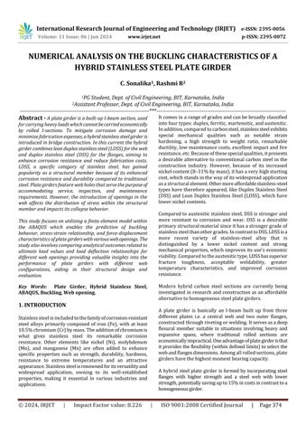
By contrasting the FE models' output with the findings of actual experiments, the models' accuracy was evaluated. Validation is done using ABAQUS 2020. Values given are Youngs modulus = 224600 MPa, Poisson's ratio = 0.225, vertical displacement load of 5 mm is applied at the midpoint.Thedimensionsweretakenfromreferencejournal [1].
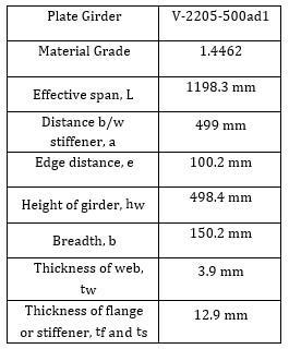
Table -1: DimensionsofplategirderforValidation
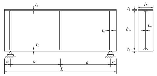
Fig -1: 2-DGeometry
Fig -2: 3-DGeometry
International Research Journal of Engineering and Technology (IRJET) e-ISSN: 2395-0056
Volume: 11 Issue: 06 | Jun 2024 www.irjet.net p-ISSN: 2395-0072
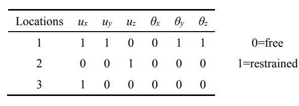
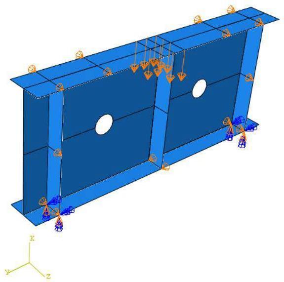
Fig -3: Boundarycondition
3.1 Results of Validation
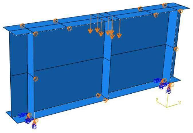
-4: Modelofplategirderwithloads
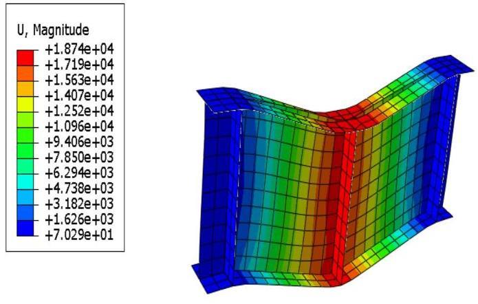
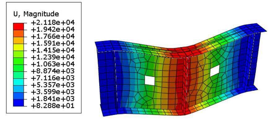
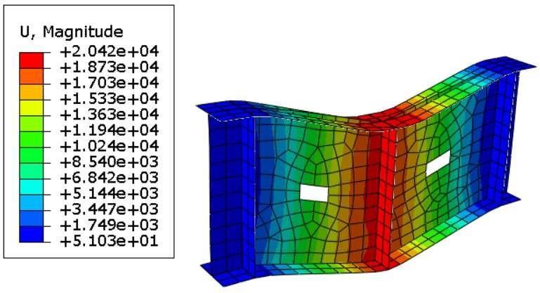
Fig -5: Deformedshapeofplategirder
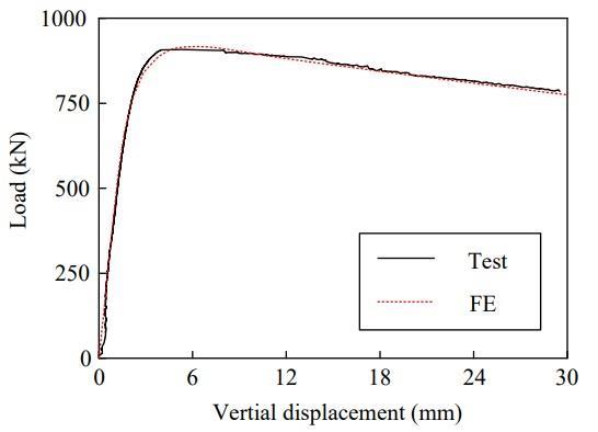
Chart -1: LoadvsDisplacementfromthereferencestudy
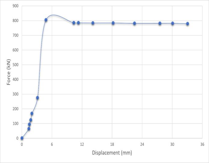
Chart -2: LoadvsDisplacementfromValidation
Model TargetDisplacement Valuesfrom thereference study
Table -2: PercentageerrorfromValidation
International Research Journal of Engineering and Technology (IRJET) e-ISSN: 2395-0056
Volume: 11 Issue: 06 | Jun 2024 www.irjet.net p-ISSN: 2395-0072
3.2 Conclusion
TheoutputofAnalytical,FEAandExperimentalanalysisare inquitegoodargumentwitheachother.Thedifference in theirvalueiswithin10%limitandisacceptable.
4. NUMERICAL ANALYSIS OF HYBRID STAINLESS STEEL PLATE GIRDER WITH OPENINGS
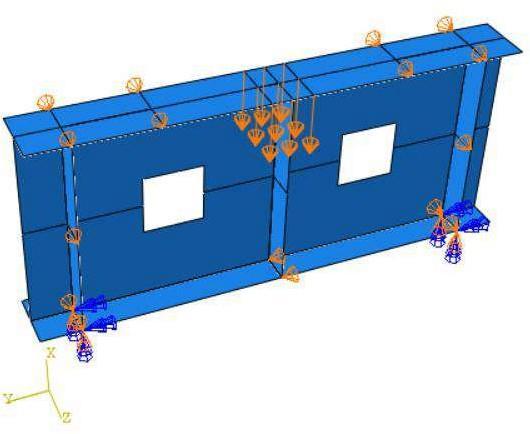
Inthisanalysis,wefocus on modellingand studyingplate girders that incorporate web openings in various shapes, namelycircular,squareandrectangular.Theseplategirders exhibitahybridconstruction,featuringawebportionmade ofDuplexStainlessSteelandflangeportionconstructedfrom LeanDuplexStainlessSteel.Thestructuralanalysisinvolves applying a midpoint load as a displacement of 5 mm, and appropriateboundaryconditionsarealsoapplied.Material propertyofthewebandflangeisgiveninTable3
Table -3: Materialpropertiesofhybridplategirder
Model Modulusof Elasticity (MPa) Poisson’s ratio YieldStress (N/mm2)
Duplex
Stainless Steel 208800 0.2 854
LeanDuplex
Stainless Steel 203000 0.2 727.5
4.1 Modelling and Results
Table -4: Designationofmodelsanalysed
Designation
Model
Model1 Circularwebopeningwithsmalldiameter
Model2 Circularwebopeningwithlargediameter
Model3 Squarewebopeningwithsmallarea
Model4 Squarewebopeningwithlargearea
Model5 Rectanglewebopeningwithsmallarea
Model6 Rectanglewebopeningwithlargearea
Table -5: Dimensionsofplategirder
4.1.1 Model 1
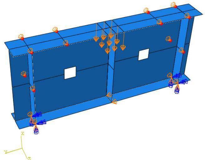
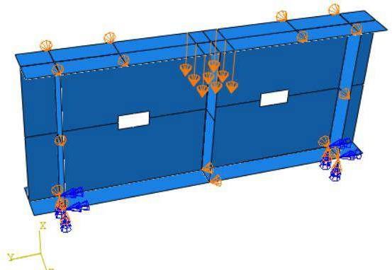
The model 1 is a hybrid plate girder with circular web openingofsmallerdiameter.Loadisappliedatthemidpoint asadisplacementloadof5mmandboundaryconditionis alsoapplied.
Forthismodelthediameterprovidedis = =83.06mm


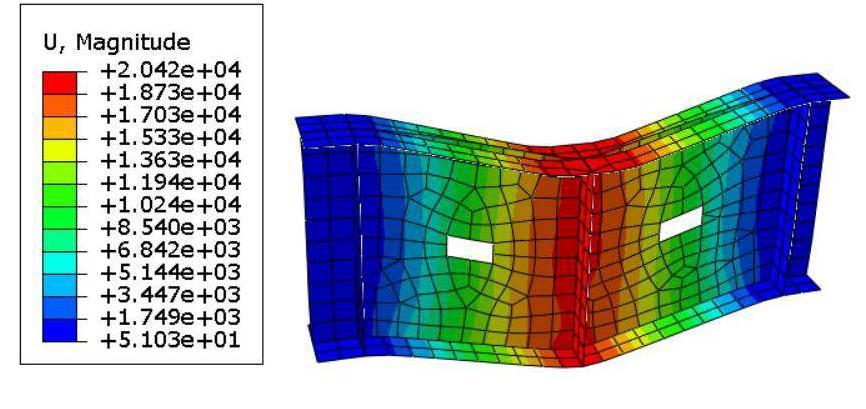
-6: Modelofhybridplategirderwithcircularwebhole
International Research Journal of Engineering and Technology (IRJET) e-ISSN: 2395-0056
Volume: 11 Issue: 06 | Jun 2024 www.irjet.net p-ISSN: 2395-0072
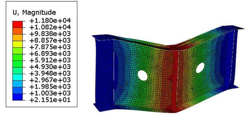
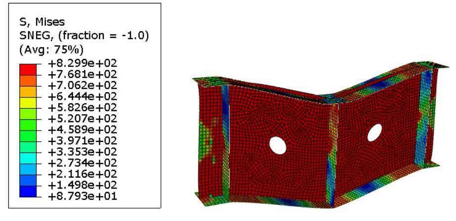
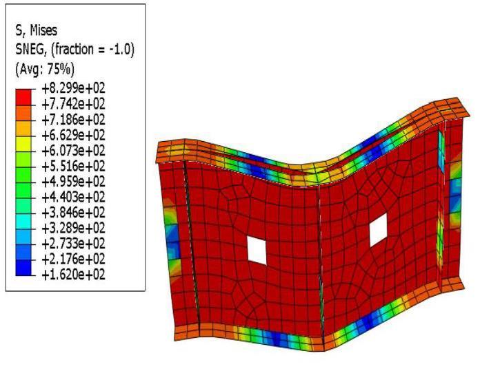
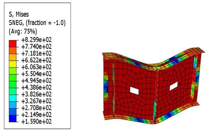
Fig -8: Von-MisesstressofModel-1
According to the Von Mises yield criterion, a material will undergo yielding if its Von mises stress under loading matchesorisabovethematerial’syieldlimitundersimple tension.
Theredcolourdenotesthemaximumstressportionsandthe blue colour denotes less stress areas. In this case, the maximumVonMisesstressnotedisrecordedas8.299e+02.
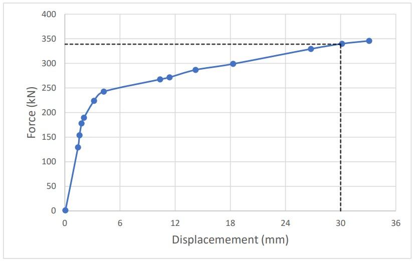
-3: ForcevsDisplacementofModel-1
Fromtheabovechartithasbeennotedthatthemaximum loadobtainedis339.9326kN ata displacementof30mm respectively.
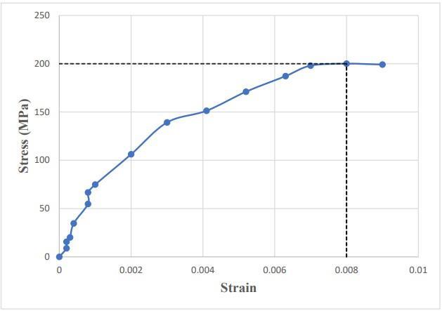
Chart -4: StressvsStrainofModel-1
Themaximumvalueofstressisapproximately200MPaata strainof0.008.
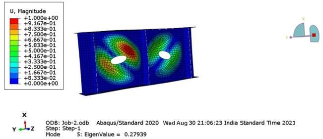
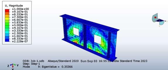
-9: BuckledshapeofModel-1
Bucklingloadistheloadunderwhichastructuralmember distortsundercompression.
Thebucklingloadistheproductofeigenvalueandtheload. Here the load is given as a displacement of 5 mm respectivelyandtheeigenvalueistakenfromFig.9.
Bucklingload=Eigenvalue×Force=0.27939×5=1.395kN
International Research Journal of Engineering and Technology (IRJET) e-ISSN: 2395-0056
Volume: 11 Issue: 06 | Jun 2024 www.irjet.net p-ISSN: 2395-0072
The model 2 is a hybrid plate girder with circular web openingoflargerdiameter.Loadisappliedatthemidpoint asadisplacementloadof5mmandboundaryconditionis alsoapplied.
Forthismodelthediameterprovidedis

= =166.13mm

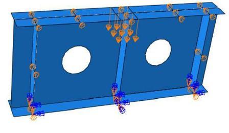
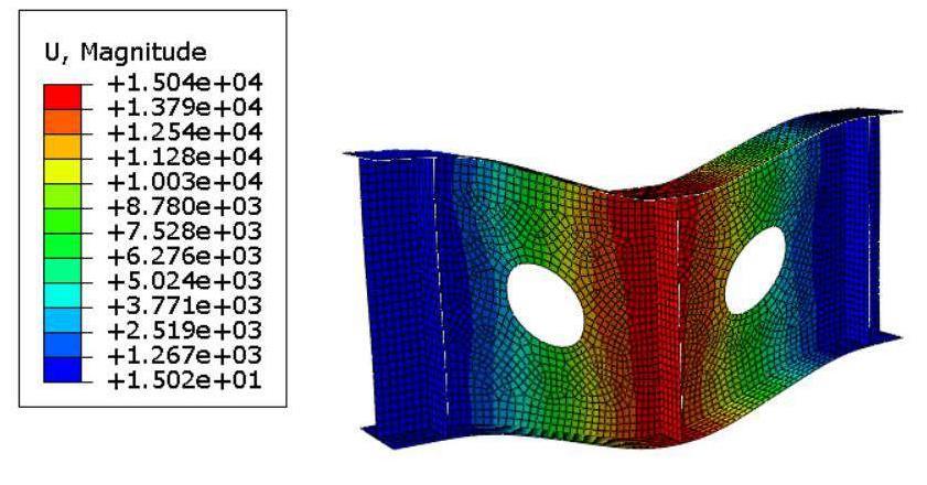
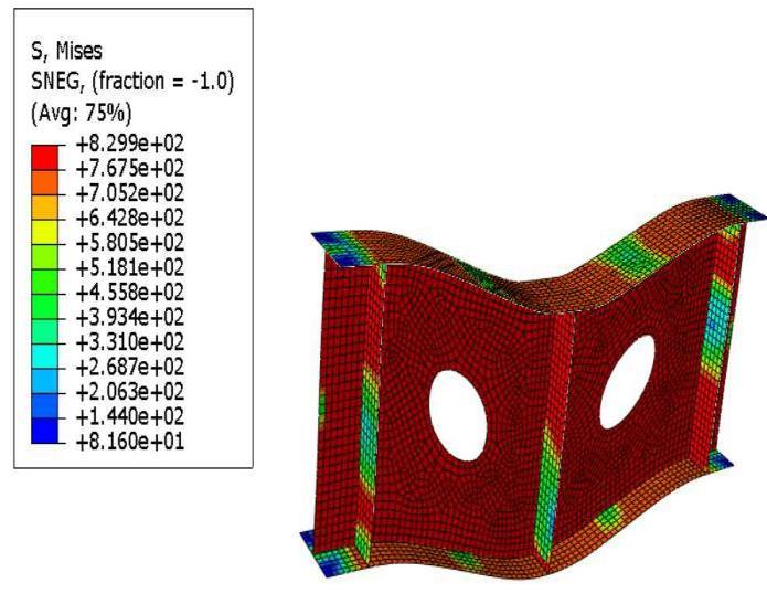
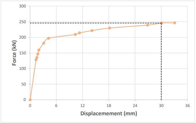
Chart -5: ForcevsDisplacementofModel-2
Fromtheabovechartithasbeennotedthatthemaximum loadobtainedis246.0370kN ata displacementof30mm respectively.
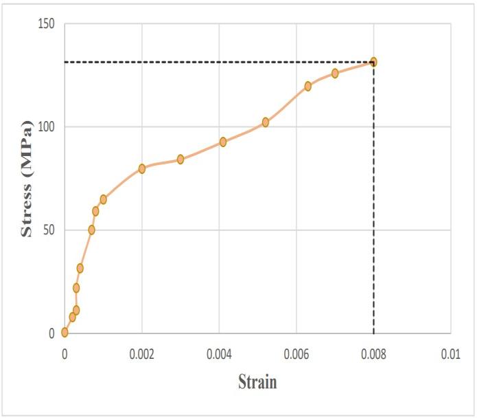
Chart -6: StressvsStrainofModel-2
Themaximumvalueofstressisapproximately131.352MPa atastrainof0.008.
International Research Journal of Engineering and Technology (IRJET) e-ISSN: 2395-0056
Volume: 11 Issue: 06 | Jun 2024 www.irjet.net p-ISSN: 2395-0072
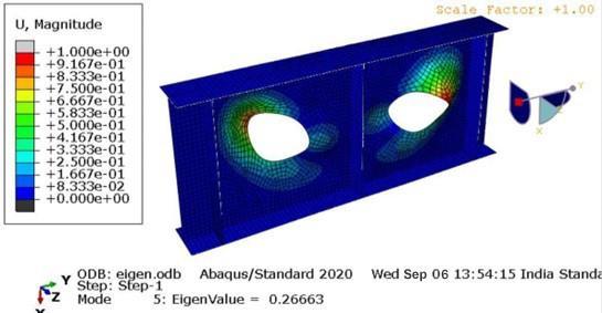
Bucklingload=Eigenvalue×Force=0.26663×5=1.333kN
The model 3 is a hybrid plate girder with square web openingofsmallerarea.Loadisappliedatthemidpointasa displacementloadof5mmandboundaryconditionisalso applied.
Areaofsquare(A)=Areaofcircle=π×r2 =π×(41.53)2 =5418.43mm2
Therefore,sideofsquare=√(A)=√5418.43=73.16mm
vsDisplacementof
International Research Journal of Engineering and Technology (IRJET) e-ISSN: 2395-0056
Volume: 11 Issue: 06 | Jun 2024 www.irjet.net p-ISSN: 2395-0072
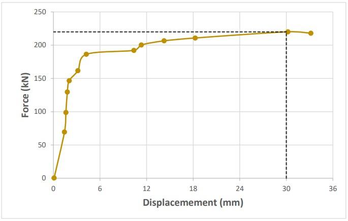
Fromtheabovechartithasbeennotedthatthemaximum loadobtainedis220.1444kN ata displacementof30mm respectively.
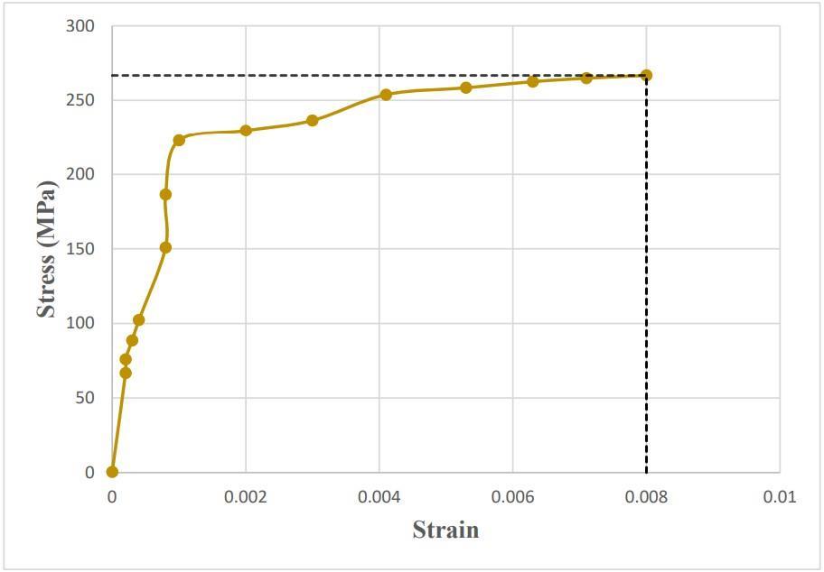
-8: StressvsStrainofModel-3
The maximum value of stress is approximately 266.7278 MPaatastrainof0.008.
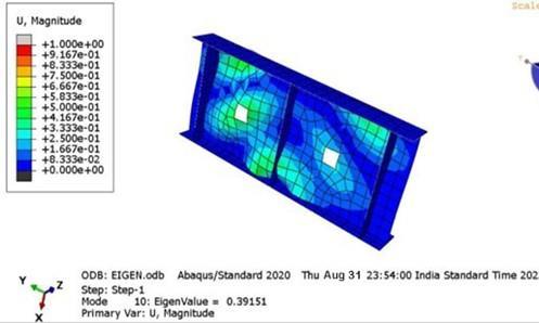
Bucklingload=Eigenvalue×Force=0.39151×5=1.965kN
4.1.4 Model 4
The model 4 is a hybrid plate girder with square web openingoflargerarea.Loadisappliedatthemidpointasa displacementloadof5mmandboundaryconditionisalso applied.
Areaofsquare(A)=Areaofcircle=π×r2 =π×(83.06)2 =21673.73mm2
Therefore,sideofsquare=√(A)=√21673.73=147.22mm
2024, IRJET | Impact Factor value: 8.226 | ISO 9001:2008
International Research Journal of Engineering and Technology (IRJET) e-ISSN: 2395-0056
Volume: 11 Issue: 06 | Jun 2024 www.irjet.net p-ISSN: 2395-0072
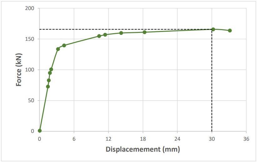
Chart -9: ForcevsDisplacementofModel-4
Fromtheabovechartithasbeennotedthatthemaximum loadobtainedis165.6970kN ata displacementof30mm respectively.
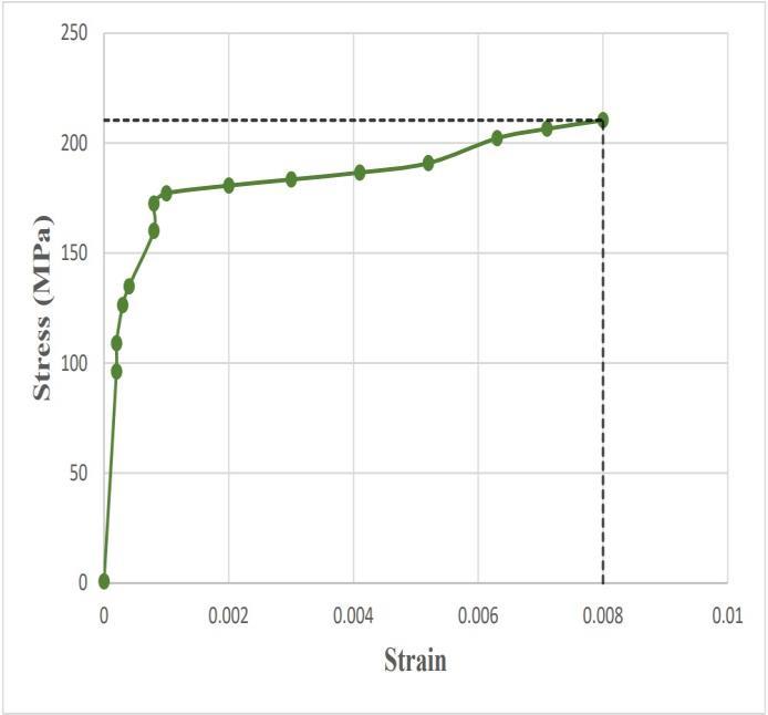
Chart -10: StressvsStrainofModel-4
Themaximumvalueofstressisapproximately210.3992MPa atastrainof0.008.
Bucklingload=Eigenvalue×Force=0.35366×5=1.765kN
4.1.5 Model 5
Themodel5isahybridplategirderwith rectangularweb openingofsmallerarea.Loadisappliedatthemidpointasa displacementloadof5mmandboundaryconditionisalso applied.
Areaofrectangle(A)=Areao
(L=2×B)Lengthofrectangle=104.1mm Breadthofrectangle=52.05mm
International Research Journal of Engineering and Technology (IRJET) e-ISSN: 2395-0056
Volume: 11 Issue: 06 | Jun 2024 www.irjet.net p-ISSN: 2395-0072
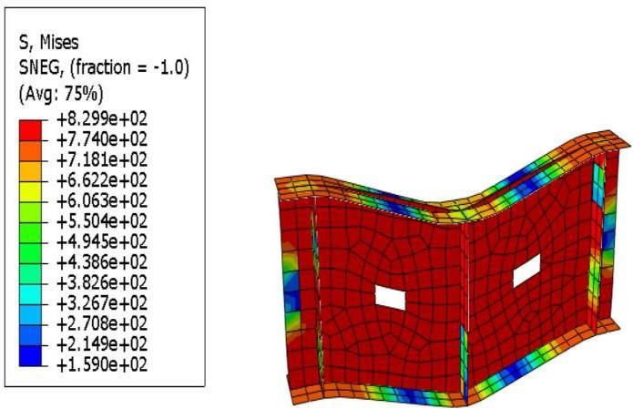
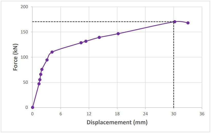
Chart -11: ForcevsDisplacementofModel-5
Fromtheabovechartithasbeennotedthatthemaximum loadobtainedis170.3625kN ata displacementof30mm respectively.
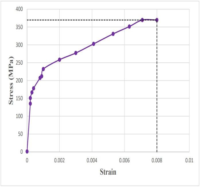
Chart -12: StressvsStrainofModel-5
Themaximumvalueofstressisapproximately369.5749MPa atastrainof0.008.
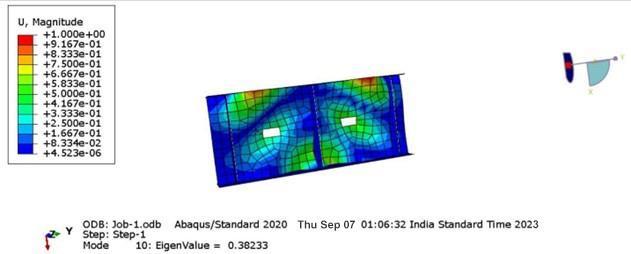
Fig -25: BuckledshapeofModel-5
Bucklingload=Eigenvalue×Force=0.38233×5=1.911kN
4.1.6 Model 6
Themodel6isahybridplategirderwith rectangularweb openingoflargerarea.Loadisappliedatthemidpointasa displacementloadof5mmandboundaryconditionisalso applied.
Areaofrectangle(A)=Areaofcircle
(L=2×B)Lengthofrectangle=208.2mm
Breadthofrectangle=104.1mm
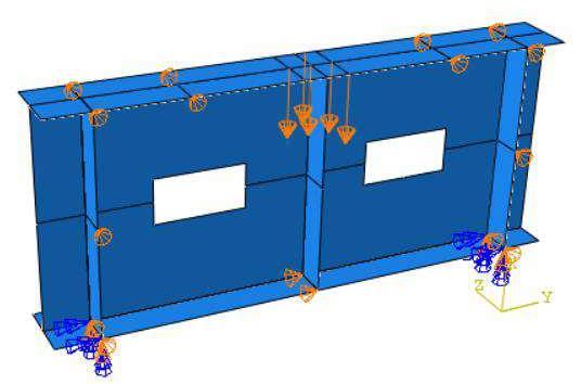
Fig -26: Modelofhybridplategirderwithrectangularweb hole
International Research Journal of Engineering and Technology (IRJET) e-ISSN: 2395-0056
Volume: 11 Issue: 06 | Jun 2024 www.irjet.net p-ISSN: 2395-0072
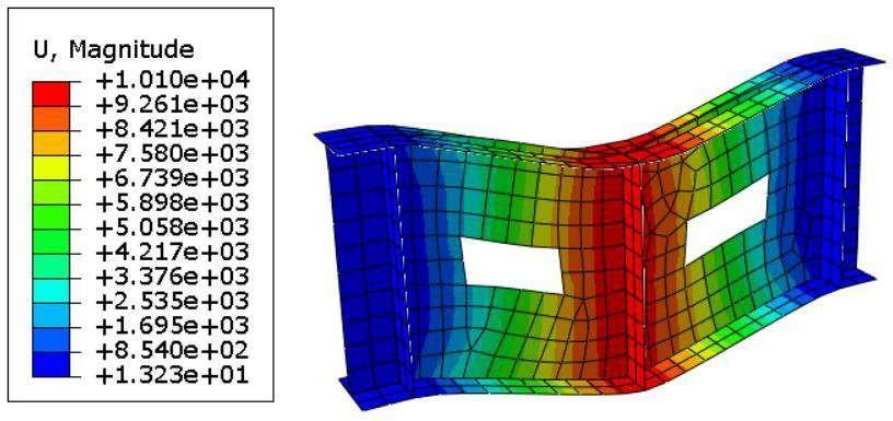
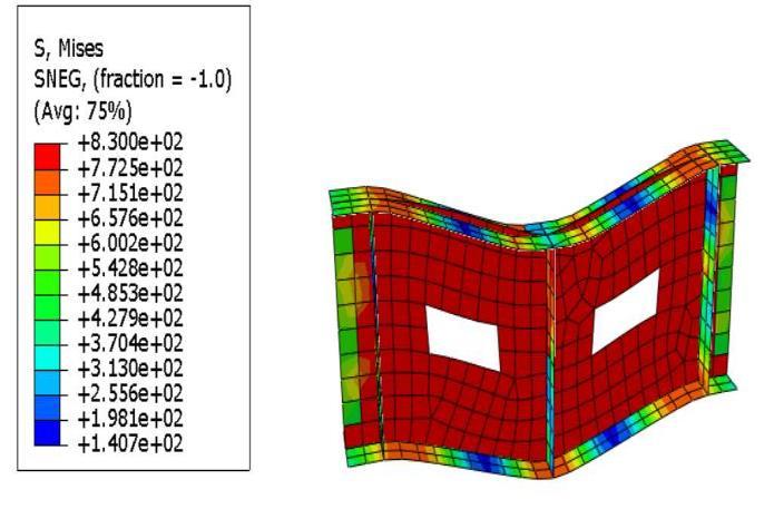
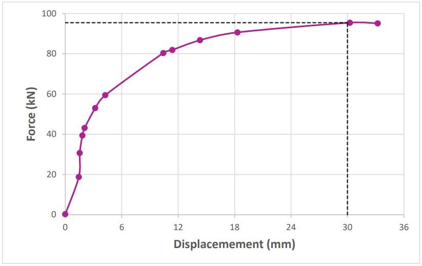
Chart -13: ForcevsDisplacementofModel-6
Fromtheabovechartithasbeennotedthatthemaximum load obtained is 95.4432 kN at a displacement of 30 mm respectively.
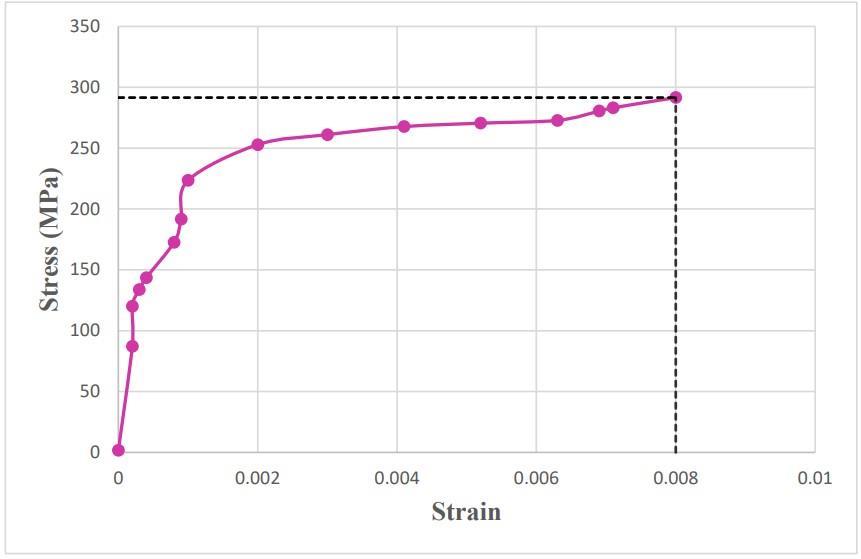
Chart -14: StressvsStrainofModel-6
Themaximumvalueofstressisapproximately291.5235MPa atastrainof0.008.
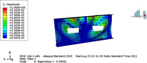
Fig -29: BuckledshapeofModel-6
Bucklingload=Eigenvalue×Force=0.34451×5=1.722kN
5.1 Comparison graph of Load- Displacement
Theloaddisplacementgraphofmodel-1,model-3,model-5 werecomparedasinChart-15,sincetheareaofopeningwas sameforthefollowingmodels
FromChart-15itisclearthatModel-1(Circularwebopening withsmalldiameter)cantakemaximumloadandModel-5 (Rectangular web opening with small area) can take the minimumload.
International Research Journal of Engineering and Technology (IRJET) e-ISSN: 2395-0056
Volume: 11 Issue: 06 | Jun 2024 www.irjet.net p-ISSN: 2395-0072
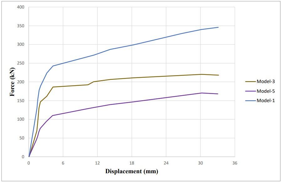
Chart -15: Comparisongraphofloaddisplacementfor Model1,3,5
Similarly,theloaddisplacementgraphofmodel-2,model-4, model-6 were compared as in Chart-16, since the area of openingwassameforthefollowingmodels.
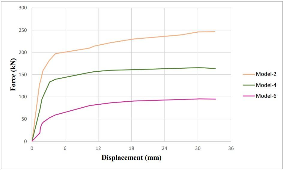
Chart -16: Comparisongraphofloaddisplacementfor Model2,4,6
FromChart-16itisclearthatModel-2(Circularwebopening withlargediameter)cantakemaximumloadandModel-6 (Rectangular web opening with large area) can take the maximumload.
IncomparisonsofChart-15andChart-16itcanbesaidthat circular web openings can carry the highest loads before experiencingsignificantdisplacement.
Thestressstraingraphofmodel-1,model-3,model-5were comparedasinChart-17,sincetheareaofopeningwassame forthefollowingmodels
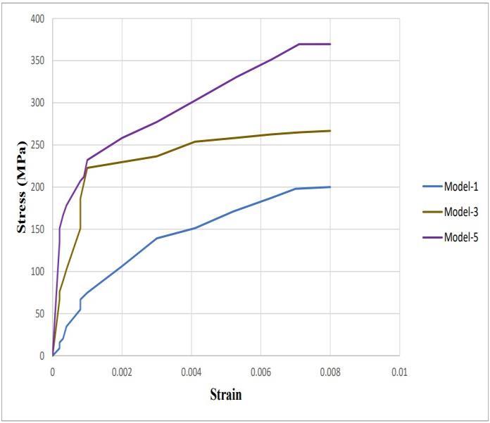
Chart -17: ComparisongraphofstressstrainforModel 1,3,5
From Chart-17 it is clear that Model-5 (Rectangular web openingwithsmallarea)issubjectedtomaximumstressand Model-1 (Circular web opening with small diameter) is subjectedtominimumstress
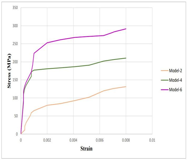
Chart -18:ComparisongraphofstressstrainforModel 2,4,6
Similarly, the stress strain graph of model-2, model-4, model-6 were compared as in Chart-17, since the area of openingwassameforthefollowingmodels.
FromChart-18itisclearthatModel-2(Circularwebopening with large diameter) is subjected to maximum stress and Model-6 (Rectangular web opening with large area) is subjectedtominimumstress.
IncomparisonsofChart-17andChart-18itcanbesaidthat astheareaofwebopeningincreases,thestressonthegirder increases. Thus, circular web openings experience lower stresscomparedtoothermodels.
International Research Journal of Engineering and Technology (IRJET) e-ISSN: 2395-0056
Volume: 11 Issue: 06 | Jun 2024 www.irjet.net p-ISSN: 2395-0072
5.3 Comparison graph of Buckling load
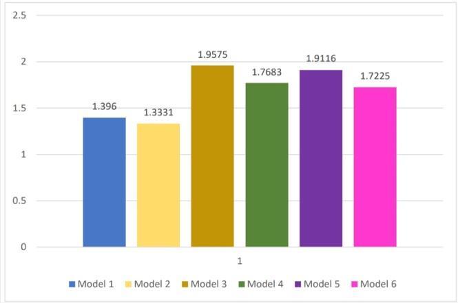
Chart -19: ComparisongraphofBucklingloads
FromChart-19itisclearthatModel-1(Circularwebopening with small diameter) and Model-2 (Circular web opening withlargediameter)haslessbucklingloadwhencompared toothermodels.
Thepresenceofacircularwebopeninginaplategirdercan indeedreduceitsbucklingloadcapacityanditisessential thatonehastocarefullyanalyzeanddesignsuchgirdersto maintainstructuralintegrityandsafety.
1) FromtheanalysisitisevidentthatHybridplategirders with circular web openings contribute better in load carryingcapacityandstructuralstiffness.
2) It appears that Hybrid plate girder with circular web opening experience lower stress compared to other modelsandhavemorefavorablestressdistribution.(As theareaofthewebopeningincreases,thestressonthe girderincreases)
3) Hybrid Plate girder with rectangular web opening is subjectedtomaximumstress.
4) Hybrid Plate girder with circular web openings have lowerbucklingloadwhencomparedtoothermodels.
5) Fordesignconsideration
• Circular openings can enhance load capacity but may require additional measures to address bucklingconcerns.
• Rectangular&squareopeningsmightbefavoredin applicationswherethestressconcentrationcanbe managedeffectively.
[1] X.W.Chen,H.X.Yuan,E.Real,X.X.Du,B.W.Schafer–“Experimental behaviour of stainless-steel plate girdersundercombinedbendingandshear”,2020. (JournalofConstructionalSteelResearch,Vol20)
[2] RohitKhobaragade,P.D.Ramteke–“Experimental StudyonBucklingBehaviourandLoadCapacityof SteelPlateGirders”,2016.(InternationalJournalfor scientificresearchanddevelopment,Vol4)
[3] RickyLalthazuala,KonjengbamDarunkumarSingh –“Structuralperformanceofhybridstainlesssteel plate girders under shear”, 2019 (Thin-Walled Structures,Vol143)
[4] X.W.Chen,H.X.Yuan,X.X.Du,Y.Zhao,J.Ye,L.Yang–“Experimentalandnumericalinvestigationofhigh strengthstainlesssteelstructures”,2018.(Journal ofConstructionSteelResearch,Vol64)
[5] ChenX.W,H.XYuan,DuXX,YangL–“Shearbuckling behaviour of welded stainless steel plate girders with transverse stiffeners”, 2018. (Thin-Walled Structures,Vol122)
[6] AGhadami,V.Broujerdian–“Shearbehaviorofsteel plategirdersconsideringvariationsingeometrical properties”,2019.(JournalofConstructionalSteel Research,Vol153)
[7] Alireza Bahrami, Mahdi Najarnasab – “Ultimate behaviorofperforatedsteelplategirdersubjected to shear loading”, 2020. (Open Construction and BuildingTechnologicalJournal,Vol14)