
International Research Journal of Engineering and Technology (IRJET) e-ISSN: 2395-0056
Volume: 11 Issue: 06 | Jun 2024 www.irjet.net p-ISSN: 2395-0072
International Research Journal of Engineering and Technology (IRJET) e-ISSN: 2395-0056
Volume: 11 Issue: 06 | Jun 2024 www.irjet.net p-ISSN: 2395-0072
Dr.N.Karpagam1 , , J.Michael Sagaya Sebatiny2, R.Jeyapratha3, S.Shanmugapriya4
1Professor& Velammal College of Engineering and Technology ,Madurai -09 , Tamilnadu 2,3,4Students & Velammal College of Engineering and Technology ,Madurai -09 , Tamilnadu ***
Abstract - The modernization of power transmission systems is essential for ensuring reliable and efficient distribution of electricity. In this context, the integration of Internet of Things (IoT) technologies into transmission line monitoringhasemergedasapromisingapproach.Thisreport presents a study on IoT-based wireless communication of transmission line parameters, aimed at enhancing the monitoring and management of power grids. The primary focusofthisresearchistodesignandimplementarobustIoT framework for real-time monitoring of transmission line parameters. The proposed system employs wireless sensor nodes strategically placed along the transmission lines to collect crucial parameters such as voltage, current, temperature, and line sag. These sensors are equipped with IoT capabilities, enabling them to communicate wirelessly withacentralmonitoringstation.
Key Words: Internet of Things(IOT),Transmission line, Transmitter and receiver , Arduino, NRF Transceiver
1.INTRODUCTION
1.1
The Internet of Things (IoT) has revolutionized variousindustriesbyenablingseamlessconnectivityanddata exchange between physical devices. Inthe realm of power transmission and distribution, IoT technologies offer immensepotentialforenhancingmonitoring,management, and overall efficiency of the electrical grid. This project focusesonleveragingIoTforthewirelesscommunicationof transmission line parameters, employing Nordic Semiconductor'sNRFseriesasacornerstoneforconnectivity. Transmissionlinesformthebackboneoftheelectricalgrid, carryinghigh- voltage electricity over long distances from power generation plants to distribution substations. Monitoring the parameters of these transmission lines is criticalforensuringgridreliability,preventingoutages,and optimizing power flow. Traditionally, this monitoring has been conducted through manual inspections or wired communication systems, which are often labor-intensive, costly,andlimitedinscalability.ByintegratingNRFmodules withsensorscapableofmeasuringparameterssuchasvoltage, current, temperature, and line sag, this project aims to develop a comprehensive IoT framework for transmission linemonitoring.Thesesensors,strategicallydeployedalong thetransmissionlines,wirelesslycommunicatewithacentral monitoringstationusingNRFmodules,therebyeliminating theneedforwiredconnectionsandenablingseamlessdata
transmission over long distances. By leveraging the capabilitiesoftheNRFseries,thisprojectseekstoovercome thelimitationsoftraditionalwiredcommunicationsystems and empower utilities with real-time insights into the operationalstatusoftransmissionlines.
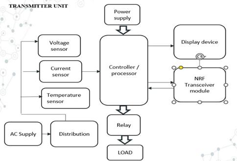
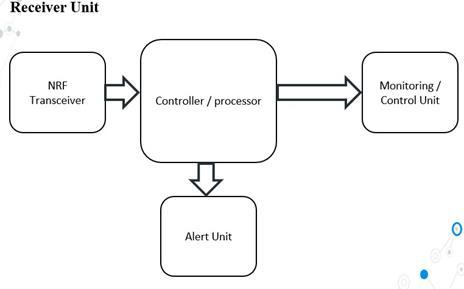
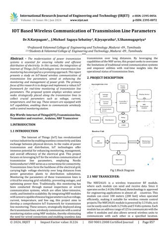
Fig1.BlockDiagram
2.1
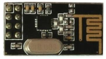
The NRF24L01 is a wireless transceiver RF module, where each module can send and receive data. Since it operatesonthe2.4GHzISMband,thetechnologyisapproved for engineeringapplicationsinalmostall countries.This module can cover 100 meters (200 feet) when operated efficiently, making it suitable for wireless remote control projects.TheNRF24L01moduleispoweredby3.3Volts,soit canbeeasilyusedinboth3.2Voltsand5Voltssystems.Each modulehasanaddressrangeof125tocommunicatewiththe other 6 modules and also allows several wireless units to communicate with each other in a specified location.
International Research Journal of Engineering and Technology (IRJET) e-ISSN: 2395-0056
Volume: 11 Issue: 06 | Jun 2024 www.irjet.net p-ISSN: 2395-0072
Therefore, mesh and other types of networks use this module.
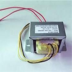
The transformer, in a simple way, can be described as a device that steps up or steps down voltage. In a step-up transformer,theoutputvoltageisincreased,andinastepdowntransformer,theoutputvoltageisdecreased.Thestepup transformer will decrease the output current, and the step-downtransformerwillincreasetheoutputcurrentto keeptheinputandoutputpowerofthesystem equal.
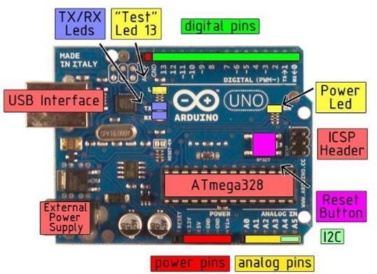
The Arduino Uno is a microcontroller board based onthe ATmega328.Ithas14digitalinput/outputpins(ofwhich6 can be used as PWM outputs), 6 analog inputs, a 16 MHz crystal oscillator, a USB connection, a power jack, an ICSP header,andaresetbutton.Itcontainseverythingneededto supportthemicrocontroller;simplyconnectittoacomputer with a USB cable or power it with a AC-to-DC adapter or batterytogetstarted
Microprocessor:
A microprocessor is a central processing unit (CPU) that servesasthebrainofacomputerorelectronicdevice.Itisa programmable integrated circuit (IC) that executes instructions to perform arithmetic, logic, control, and input/output(I/O)operations.
Microcontroller:
Amicrocontrollerisacompactintegratedcircuit(IC) that combines a microprocessor core with memory, input/output(I/O)peripherals,andotherfunctionalblocks onasinglechip.
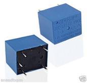
A relay is an electrically operated switch that uses an electromagnet to mechanically control the opening or closing of one or more electrical contacts. It is commonly used in electrical circuits to control the flow of current basedontheactivationofanexternalsignalorinput.Relays consist of a coil, an armature, one or more stationary contacts,andoneormoremovablecontacts.
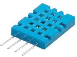
DHT11SensorandItsWorkingHumidityisthemeasureof watervapourpresentintheair.Thelevelofhumidityinair affectsvariousphysical,chemicalandbiologicalprocesses. Inindustrialapplications,humiditycanaffectthebusiness costoftheproducts,healthandsafetyoftheemployees.So, insemiconductorindustriesandcontrolsystemindustries measurement of humidity is very important. DHT11 is a digitaltemperatureandhumiditysensor
International Research Journal of Engineering and Technology (IRJET) e-ISSN: 2395-0056
Volume: 11 Issue: 06 | Jun 2024 www.irjet.net p-ISSN: 2395-0072
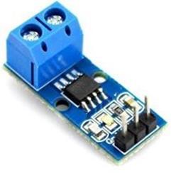
The ACS712 is a fully integrated, hall effect-based linear current sensor with 2.1kVRMS voltage isolation and a integrated low-resistance current conductor. Technical terms aside, it’s simply put forth as a current sensor that usesitsconductortocalculateandmeasuretheamountof currentapplied.
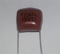
2.8 BYEPASS CAPACITOR:
Abypasscapacitor,alsoknownasadecouplingcapacitor,is anelectroniccomponentusedinelectricalcircuitstoshunt unwantedhigh-frequencynoisetogroundandstabilizethe voltage levels at specific points in the circuit. Bypass capacitors are typically placed in parallel with the power supply lines or signal lines of integrated circuits (ICs) or other active components. They provide a low-impedance pathforhigh- frequencynoisecurrentstoflowtoground, preventing them from affecting the performance of the circuit.
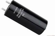
2.9 FILTER
A filter capacitor, also known as a smoothing capacitor or reservoir capacitor, is an electronic component used in electricalcircuitstofilterorsmoothvariationsinvoltageor current.Inalternatingcurrent(AC)circuits,filtercapacitors areoftenconnectedinparallelwithaloadorpowersupply to reduce or eliminate fluctuations in voltage caused by variations in the input power source or by switching components.Theystoreelectricalchargeduringperiodsof high voltage and release it during periods of low voltage, effectively smoothing out the waveform. In direct current
(DC)circuits,filtercapacitorsarecommonlyusedinpower supplies to remove ripple voltage or noise caused by the rectificationprocess.
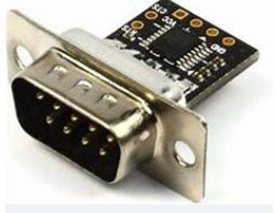
ATTL(Transistor-TransistorLogic)converterisadeviceor circuit that is used to convert signals between TTL logic levels and other logic standards, such as CMOS (Complementary Metal-Oxide-Semiconductor) or RS-232 (RecommendedStandard232).
A TTL converter may be necessary when interfacing betweensystemsorcomponentsthatoperatewithdifferent logicstandards.Forexample:
• TTL to CMOS Conversion: CMOS devices operate with logic levels typically ranging from 0 to the supply voltage (Vcc). A TTL to CMOS converter may be used to adaptsignalsfromTTLlogiclevelstoCMOSlogiclevels.
A bridge rectifier is an electrical component or circuit configurationusedtoconvertalternatingcurrent(AC)into direct current (DC). It is commonly used in power supply circuitstoprovidea constantDCoutput fromanACinput source. A bridge rectifier typically consists of four diodes arrangedinabridgeconfiguration,hencethename"bridge." Thediodesareconnectedinsuchawaythattheyformaloop orbridge,withtwodiodesconductingduringeachhalf-cycle of the input AC waveform. This arrangement allows the bridge rectifier to rectify both the positive and negative halvesoftheACwaveform,resultinginafull-waverectified output.Duringthepositivehalf-cycleoftheACinputvoltage, twodiodesconductcurrent,allowingittoflowthroughthe load in one direction. During the negative half-cycle, the othertwodiodesconduct,allowingcurrenttoflowthrough
International Research Journal of Engineering and Technology (IRJET) e-ISSN: 2395-0056
Volume: 11 Issue: 06 | Jun 2024 www.irjet.net p-ISSN: 2395-0072
the load in the opposite direction. As a result, the output voltageacrosstheloadisalwayspositivewithrespecttothe commonterminal,providingacontinuousDCoutput.
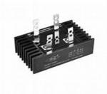
Fig.11.BridgeRectifier
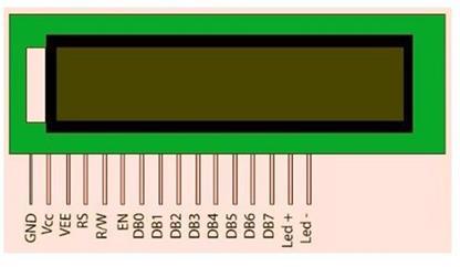
LCDisessentiallyusedforexposetheinformation.Herewe areusing2x16LCD.Itisusedtodisplaynumbers,textsand graphics. This is in contrast to LEDs, which are limited to numbers and characters. The LCDs are fragile with only a fewmillimeterthickness.SincetheLCDsutilizelesspower, theyareefficientwithlowpowerelectroniccircuits,andcan bechargedforlongterms.TheLCDsdon’tprovokelightand solightisneededto readthedisplay.TheLCDshavelong lastinglifeandawideoperatingtemperaturerange
3. RESULTS:
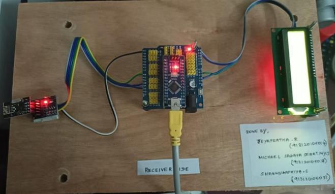
Whenthereceiversideconnectedwiththesupplyorwhenit connectedwiththeArduinoreceivercodeitgivestheoutas
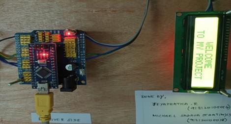
Fig15:Initialoutputofthereceiverside
Whenthecurrent(inmA)intheloadiswithinthegiverange whichissetusingthecodewritteninArduinosoftware,the resultantoutputwillbe “Normal current”
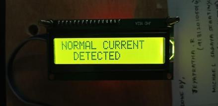
Fig:16Normalcurrent
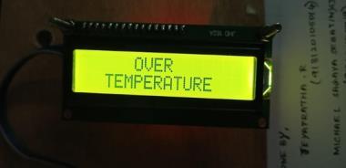
Whenthetemperatureoftheloadisexceedsthegiverange whichissetusingthecodewritteninArduinosoftware,the resultantoutputwillbe “Over temperature”.
International Research Journal of Engineering and Technology (IRJET) e-ISSN: 2395-0056
Volume: 11 Issue: 06 | Jun 2024 www.irjet.net p-ISSN: 2395-0072
[1] M.-S.Kang,Y.-L.KeandH.-Y.Kang,"Zigbeewireless networkfortransformerloadmonitoringandtemperature sensitivityanalysis",Proc.IEEEInd.Appl.Soc.Annu.Meeting, pp.1-12,Oct.2023.
[2] J.FrolecandM.Husak,"Wirelesssensorsystemfor overheadlineampacitymonitoring",Proc.8thInt.Conf.Adv. Semicond.DevicesMicrosyst.,pp.211-214,Oct.2022.
[3] Y. Yang, F. Lambert and D. Divan, "A survey on technologiesforimplementingsensornetworksforpower delivery systems", Proc. IEEE Power Energy Soc. Gen. Meeting,pp.1-8,Jun.2019.
[4] A. A. Khan, N. Malik, A. Al-Arainy and S. Alghuwainem, "A review of condition monitoring of undergroundpowercables",Proc.Cond.Monitor.Diagn.,pp. 909-912,Sep.2022.
[5] R.Nagarajan, R.Yuvaraj, V.Hemalatha, S.Logapriya, A.Mekalaand S.Priyanga," Implementation of PV - Based Boost Converter Using PI Controller with PSO Algorithm, "InternationalJournalofEngineeringAndComputerScience (IJECS),
Volume6,Issue3,pp.20477-20484,March2017
[6] R. Sidqi, B. R. Rynaldo, S. H. Suroso, and R. Firmansyah,―Arduinobasedweathermonitoringtelemetry systemusingNRF24L01+,‖IOPConferenceSeries:Materials Science and Engineering, vol. 336, no. 1, 2018. doi: 10.1088/1757-899X/336/1/012024
[7] B. Li, Z. Li, and L. Wei, ―The design of remote temperaturemonitoringsystem,‖
AIP Conference Proc., vol. 1864, 2017. https://doi.org/10.1063/1.4992939