
International Research Journal of Engineering and Technology (IRJET) e-ISSN: 2395-0056
Volume: 11 Issue: 05 | May 2024 www.irjet.net p-ISSN: 2395-0072
International Research Journal of Engineering and Technology (IRJET) e-ISSN: 2395-0056
Volume: 11 Issue: 05 | May 2024 www.irjet.net p-ISSN: 2395-0072
Anish Sonawane1 , Paritosh Pisal2 , Shubham Shinde3 , Kunal Sonawane4,Prof. Vijay Kharade5
1Anish Sonawane SPPU (Jaywantrao Sawant College of Engineering)
2Paritsoh Pisal SPPU (Jaywantrao Sawant College of Engineering)
3Shubham Shinde SPPU (Jaywantrao Sawant College of Engineering)
4 Kunal Sonawane SPPU (Jaywantrao Sawant College of Engineering)
5 Asst.Professor Vijay Kharade, Dept. of Mechanical Engineering, JSCOE, Maharashtra, India ***
Abstract - Laser Beam Machining is a type of modern machining process which includes the use of LASER (Light Amplification by Stimulated Emission of Radiation)to remove the material from the surface of a workpiece. The motive behind choosing this topic as a subjectofstudyistounderstand modern machining trendand useofsome moderntechnologies for research regarding development in the field. First, various research papers of many known authors in the field are studied thoroughly. Then experiments are carried out after selection of material for the research. Finally modern and advanced tools utilized to explore results ofexperimentsin the virtual environment. The experiments have been carried out considering various parameters necessary in the fieldofLaser Beam Machining. One of the key LBM processes which are extensively used in the industry i.e., Fiber LaserMachiningare selected for the purpose of the study. Then the results of experiments will be fed to a DOE (Design of Experiments)tool to analyze the results from the experiments and compare them
Key Words: Condition monitoring, Tool Wear, Surface Roughness, Vibrations, LBM, DOE, Reduction in bur formation
Theuseoftraditionalmachiningtechnologiesislimiteddue totheemergenceofinnovativeengineeringmaterials,severe design requirements, intricate shape, and unusual size of workpiece. As a result, it was decided to design some advanced machining processes (AMPs), which are nonconventional machining procedures. Numerous advanced machining processes(AMPs)areusedintoday'sindustry, buteachhasitsownsetofconstraintsintermsofworkpiece material, shape, and other factors. Advanced machining processes are beam machining processes, jet machining processes, electro discharge machining, ultrasonic machining Laser Beam Machining (LBM) is a cutting techniquethatisusedtoshapeawiderangeofengineering materials.cutting,drilling,marking,welding,sinteringand heat treatment are just a few of the applications for laser beams. Although the laser can be used for turning and
milling,itsmajorapplicationisinthecuttingofmetallicand non-metallicsheets.
SolidStatelasersandGasLasersaretwotypesoflasersused inmachiningapplications.Nd:YAGlasers,Fiberlasers,Diode lasers,andTi:Sapphirelasersarethedifferenttypesofsolid state lasers. Solid state lasers are categorized as lamp pumpedand diode pumped dependon the type of energy sourceusedforexcitationCO2Lasers,ExcimerLasers,and CopperVapourLasersarethethreetypesofgaslasersused in machining. Lasers are categorized as Continuous Wave (CW)andPulsedWave(PW)basedontheirwaveproperties.
Melting, vaporization, and chemical degradation are all stages of the material removal mechanism during LBM. Whenalaserbeamwithahighenergydensityisfocusedon the work surface, the work volume is heated and transformedintoamolten,vaporized,orchemicallyaltered stateasthethermalenergy is absorbed, that can be easily removed with the helpofahigh-pressureassistgasjet
Drilling (1-D), cutting (2-D) and grooving, turning and milling(3-D), and micromachining of various workpiece materials arethe most common LBM configurations. For drillinghundredsofcloselyspacedholesinstructures,laser beam drilling has become the acknowledged and cost effectivemethod.Trepanandpercussionlaserbeamdrilling aretwoformsoflaserbeamdrilling.Trepandrillingentails cuttingallthewayaroundthehole'scircumference, withno relative movement of the laser or workpiece, percussive drilling‗punches'directlythroughtheworkpiecematerial. Thereductioninprocessingtimeisanaturalbenefitofthe laserpercussiondrillingmethod.
International Research Journal of Engineering and Technology (IRJET) e-ISSN: 2395-0056
Volume: 11 Issue: 05 | May 2024 www.irjet.net p-ISSN: 2395-0072
The study of various parameters on cutting force, surface roughnessandflankwearwereexperimentallyconducted on In-situ Al6061-TiC. When cutting speed increased the cuttingforceandsurfaceroughnessdecreased.Flankwear increasedwithincreaseincuttingspeed
[1]. Laser cutting of 6061-T6 aluminium alloy carried out experimentally.Thecuttingspeedincreaseswiththelonger pulseduration.Thekerfwidthandtaperanglewereaffected bybeamtraveldirection
[2].Surfaceroughnesswastestedbyvaryingvariouscutting parametersontungstenalloy.Theoptimumvaluesofcutting speed and laser power were determined for achieving uniformsurfaceroughness
[3].Theeffectofpaintremovalonfatiguecrackgrowthwas investigated. The comparison of crack length on paint stripped and unstrapped was done. It was observed than thereinnochangeinconductivity.
[4]. The effect of cutting parameters on kerf width and surface roughness were tested. Itwas concluded that kerf widthandsurfaceroughnessincreaseswithincreaseinlaser power
[5].Thetestingofthermographyprocesswasdoneinorder toassurethequality.Quasistatictensiletestsconcludedthat theopenholespecimenaresensitivetoexpansionofHeat AffectedZone
[6]. Effect of different process parameters like pulse frequency,pulsewidthandspeed ondimensionalaccuracy, surfaceroughnessandburrthicknesswereinvestigated.It wasobservedthatfrequencyaffectsthesurfaceroughness andburrthickness.Dimensionalaccuracycancontrolledby changingpulsewidth.
[7].Optimumvaluesoftheparameterskerfwidthandkerf deviation found while performing experiment on cutting aluminiumalloybylaserbeamcutting.Smallchangeinkerf width after increasing laser power and gas pressure was observed.
3.1INTRODUCTION TO DESIGN OF EXPERIMENTS(DOE):-
Design Of Experiments (DOE) is a method used in almost everyfieldofEngineering.Itisusedforeffectivesolvingof problems aswell asfor improvisation andoptimizationof ProductDesignsorManufacturingProcesses.Somecommon applications Of DOE in the field of Engineering include identificationofproperdesigndimensionsandtolerances, achievingrobustdesigns,generatingpredictivemathmodels that describe physical system behavior, and determining idealmanufacturingsettings.InDesignofExperimentsinthe fieldofEngineering,themainpurposeofanexperimentis to
predict the outcome by introducing a change of the preconditions, which is represented by one or more independentvariables,alsoknownas"inputvariables".
InDOE,thechangeinanyoneormoreindependentvariables isgenerallyhypothesizedtoresultinachangeinoneormore dependablevariables,alsoknownas"outputvariables".In experimental design, the main concerns include the establishmentofvalidityandreliability.Theseconcernscan be solved by carefully choosing the independent variable, reducingtheriskofmeasurementerror,andensuringthat thedocumentation of the method is sufficiently detailed. DesignofExperimentsisdonewiththehelpofDOESoftware. These DOE software have evolved from time to time in accordancewiththeadvancementsintheEngineeringfield. SomeoftheleadingsoftwareusedforDesignofExperiments are JMP, Minitab, Cornerstone & Design-Expert. For our projectwork,wehaveselectedDesign-ExpertVersion13for designingexperiments.
Inthisproject,wehaveusedBox-BehnkenResponseSurface Method for the analysis of outputs of our actual experimentations of Laser Beam Machining (Laser Cutting) on Aluminum 6061 Alloy material. The use of Design-ExpertSoftwarehelpedustoaccuratelyanalyzeand determinetheaccuracyoftheoutcomesofthetypesofLaser CuttingOperation(FiberLaser).
As mentioned earlier, the Box-Behnken Response Surface MethodisusedforDOEinthisproject.Thefollowingsteps arefollwedinthedesigningof'experimentsinthisproject
1.Firstly, the experimental data for Fiber laser Cutting is collected.
In the Box-Behnken Response Surface tab of Design2.ExpertSoftware,alltheexperimentaldataofbothcutting operations (Input Parameters or Factors) is fed in the columnsgiveninthefirstwindow.
3.Then in the next step, the number of columns for responses(OutputParameterorresponses)andtheirdetails (Nameoftheresponse&itsunit)arementioned.
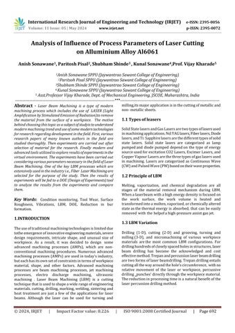
4.Then the Design-Expert Software presents with a table similartothatpresentedbelow
Volume: 11 Issue: 05 | May 2024 www.irjet.net p-ISSN: 2395-0072
As mentioned earlier, the Box-Behnken Response Surface MethodisusedforDOEinthisproject.Thefollowingstepsare followedinthedesigningofexperimentsinthisproject.
1. Firstly,theexperimentaldataforFiberLaserCuttingis collected.
2. In the Box-Behnken Response Surface tab of DesignExpert Software, all the experimental data of both cuttingoperations(InputParametersorFactors)isfed inthecolumnsgiveninthefirstwindow.
3. Then in the next step, the number of columns for responses(OutputParameterorresponses)andtheir details(Nameoftheresponse&itsunit)arementioned.
4. ThentheDesign-ExpertSoftwarepresentswith atable likethatpresentedbelow
5. Then in the next step, we enter the outputs of the experiments which we performed to analyze their relatability, reliability, and their validity. After filling the responses, we get a table like that presented below.
6. Afterenteringtheresponsesfromactualexperiments, we can begin the analysis of the responses to check fortheirvalidity.Theoptionwegetafteristoconfigure theresponsewewishtoanalyze.Thewindowsimilar tothefollowingappears
7. Afterthe‗StartAnalysis‘option,wegetseveralanalysis windowslikeModelSummary, FitSummary,etc.The importantofall andtheone whichweareconcerned aboutis ANOVA (Analysis ofVariance).ANOVA, with the help of suggested Fit model, determines and presents us with the significance of our model along with other factors of which Lack of Fit is important. LackofFitindicatestheabsenceofcorrectnessinour model. According to ANOVA of Design-Expert, the ModelofourexperimentmustbesignificantandLack ofFitmustbeinsignificant
8. After getting the ideal model of the experiment, it becomes multiple factors are available in DesignExpert software. The optimization of these is also possiblein caseofidealmodelwhichstillhelpsusto obtaindesiredoutcomes fromtheavailablemodelof theexperiment.easyforustoanalyzetheoutcomesof our model withthehelpof different typesof graphs. Various2Dimensionalaswellas3-Dimensionalgraphs withsinglefactor
1. The material selected for this research is AluminiumAlloy(AL6061).
2. ThereasontoselectAluminiumastheresearch material is because it has wide number of applications.
3. It is extensively used in defence sectors like Army,Navy&AirForceandinothersectors for whichweareconductingthisresearch.
4. Aluminiumalongwithbeingadurablematerial, is very workable i.e., one canperform various operations on it without disturbing its original physicalproperties.
International Research Journal of Engineering and Technology (IRJET) e-ISSN: 2395-0056
Volume: 11 Issue: 05 | May 2024 www.irjet.net p-ISSN: 2395-0072
5. Machining operations like drilling, welding, etc. can be done easily on Aluminium without breaking it, which makes it a very reliable materialthatistrustedbythedefencesector.
6. This is because it is corrosion resistant, very durable, temperature resistant and it has high tensilestrength.
7. For experimentations, a Aluminium plate of 250mm*250mmlengthandbreadthrespectively and8mmthicknesswasselected.
1. After the selection of material, the actual experimentationworkbegan.
2. Firstly, was the task to select the material to carryoutexperiments.So,fortheexperiments AL6061wasselected.
3. Then the task was to find Laser cutting machinestocutthematerial.
4. ForthestudyofLaserBeamMachine,wecarried out study at Anand Lasers, Narhe for amonth. ThereoverallworkingofLaserBeam Machine wasstudied.
5. For Fiber Laser Machining experimentations, a machineatAnandLasers,Narhe wasselected.
6. ForFiberLasercutting,BystronicAMADAFiber machine at Anand Lasers was selected. The inputpowercapacityofthismachineis9KW.
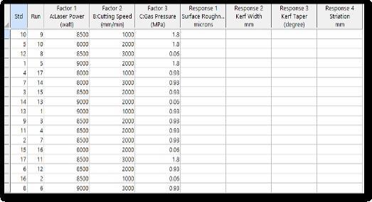
1. For Fiber Laser cutting, after the selection of Laser CuttingMachineatAnandLaser,lasercuttingoperations wereperformed according to the experiment design providedbyDesign-ExpertSoftware.
2. AfterplacingtheAluminiumplateonmachinebedfor cutting, input parameters i.e., Power, Cutting Speed & Gas Pressure are varied according to the design suggestedbyDesign-ExpertSoftware.
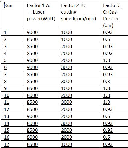
3. Design-Expert Software provided 17 runs for Fiber Laser cutting design. For the types of machining processes,theinputparameterswerechangedforevery run according to the provided design with the help of controller setup screen available for changing parametersofthemachine.
4. The controller is operated by a trained operator who changestheparametersaccordingtothe requirements ofthecustomer.Thecontrollerscreenisaspresentedin theFig.3.1
5. Thecontroller is operated bya trained operator who changes the parameters according to the requirementsofthecustomer.
1. The analytical simulation for the Laser Beam Machining project is done. As mentioned earlier, various advanced and wide range of features and graph types of Design-Expert software are used in thisproject.
2. Also,asmentionedearlier,thisprojectiscarriedout for one key types of Laser Beam Machining operationsi.e.,FiberLaserMachining.
3. With the help of analytical tools in Design-Expert software,wehavecomparedtheoutputparameters ofbothLaserMachiningoperations.
4. Theoutputparameterstakeninconsiderationfor thisprojectareSurfaceRoughness,KerfTaperAngle, &KerfWidth,Striation.
5. All the steps mentioned in Section 3 Design of proposed work were followed to carry out the analysis of the outputs obtained from the experimentations.
6. Afterconductingtheexperiments,theoutputswere fed in Design-Expert Software & analysis of these outputswasconductedaccordingly.
7. As required for the ideal experimental data to analysis it with more efficiency, the model of designed experiments for every output parameter
International Research Journal of Engineering and Technology (IRJET) e-ISSN: 2395-0056
Volume: 11 Issue: 05 | May 2024 www.irjet.net p-ISSN: 2395-0072
wasobtained to be significant & Lack of Fit was obtainedinsignificant.
8. Thus, after obtaining optimal conditions for analyzing, 3D Surface Graphs for every output parameterofthetypesofLasersCuttingOperations werecompared.
9. The final readings for CO2 Laser Cutting are as mentionintable.
10. Withthehelpofthesefactors&responses(Input &Outputparameters)oftheactualexperiments,the observationtableswereprepared.
11. Based on this data, the analysis of every output parameter is performed. All the models of every responseareobtainedtosignificant&lacksofFitare not significant. This means that all the models are idealandalltheoutputsarevalid&reliable.
12. Thegraphicalanalysisisalsoperformedforthese parameters.
13. Tocomparebothtypes ofLaserBeamMachining, #DResponseSurfaceGraphstoanalyzeandfindthe rangeofoptimalinputparametersforeveryoutput parameterutilized.
14.TheGraphicalAnalysis&Comparisonfortheoutput parametersofLaserBeamOperationsareasfollows.
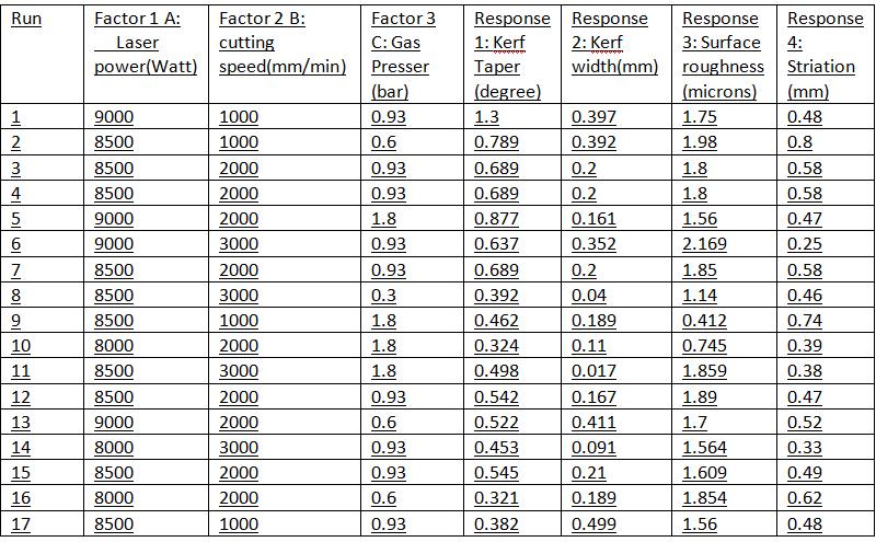
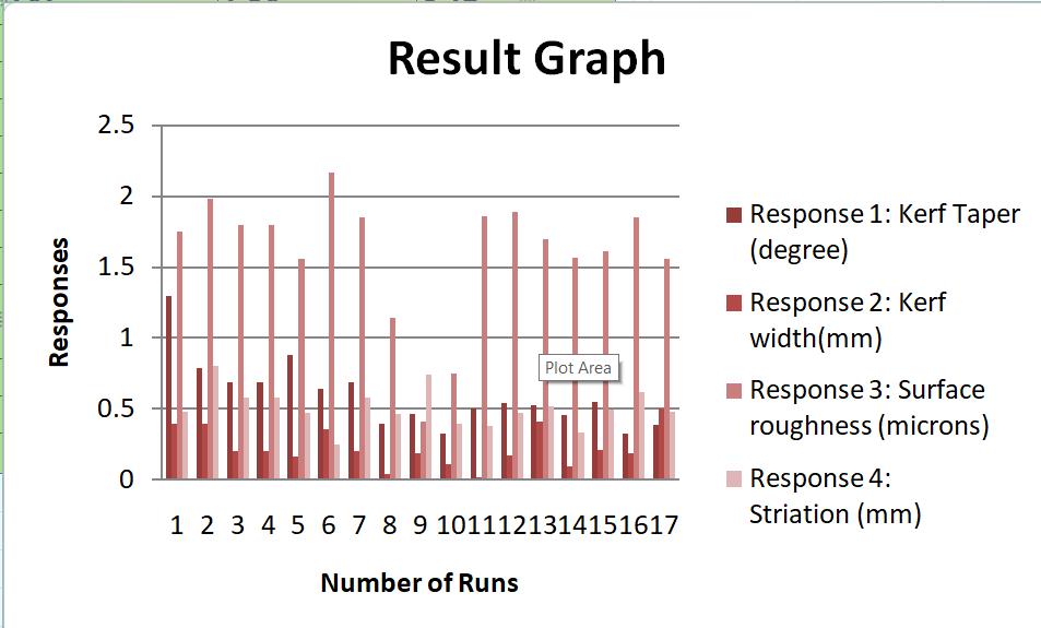
Table 4.2 :- Graphical Results
Selected material was Aluminum 6061 Alloy. Fiber as a Laserwaschosentocutthe selected material.Considered process parameter like cutting speed, laser power, gas pressure(bar). Selected performance parameters like kerf width, kerf taper angle, surface roughness, HAZ(Heat affected zone), Striation. Using Design of Experimentation software V13 by using Box Behnken method generated a table.Itwasobservedthatminimumsurfaceroughnesswas obtainedwhenlaserpowerwas8500w,cuttingspeedwas 1000mm/minandgaspressurewas1.8Mpa.Theminimum valueofkerfwidthwasobtainedforlaserpowerwas8500 w, cutting speed was 3000 mm/minandgaspressurewas 1.8Mpa.
[1] D Sai Chaitanya Kishore et. al., Investigation of cuttingforce,surfaceroughnessandflankwearinturning ofIn-situA16061-TiCmetalmatrixcomposite‖,Procedia MaterialScience6(2014)1040-1050,ICMPC2014
[2] C. Leone et. al., An investigation on Nd: YAG laser cuttingofA16061T6alloysheet‖,ProcediaCIRP2864-69, (3rd CIRPGlobalWebConference)2015
[3] Derzija Begic-Hajdarevic et. al., Analysis of the influence of cutting parameters on surface roughness in laser cutting process of tungsten‖, DAAAM Proceedings, 2017
[4] Marko Yanishevsky, Effect of Atmospheric Plasma Paint Removal on the Fatigue Performance of 2024-T3 Aluminium Alloy Sheet‖, Journalid=1753, Vol.6 No.1, January2018
[5] S.D Jadhavet.al., StudyofLaserMachiningofA16061 byFibreLaser‖,JETIR,Volume6,Issue4,2019
International Research Journal of Engineering and Technology (IRJET) e-ISSN: 2395-0056
Volume: 11 Issue: 05 | May 2024 www.irjet.net p-ISSN: 2395-0072
[6] Michael Rose, Mechanical Properties of RemoteLaser Cut CFRP and Thermographic Laser-Process Monitoring‖,journalid=174,vol.1.1No.8,2020
[7] Irene Buj-Corral et. al., Effect of Process Parameters on the Quality of Laser-Cut Stainless Steel Thin Plates‖, ArticlepublishonMDPI2021
[8] P. P. Kharche and Dr Vijay H Patil, Experimental InvestigationofKerfWidthandKerfTaperinFiberLaser Cutting of Aluminium Alloy‖, 8.4.6 Vol. 8, No. 4, PP. 2530,IJIES2023


AnishSonawane
B.EMechanical
Jaywantrao sawant college of engineering,Pune sonawaneanish88@gmail.com
ParitoshPisal
B.EMechanical
Jaywantrao sawant college of engineering,Pune paripisal2000@gmail.com
ShubhamShinde
B.EMechanical
Jaywantrao sawant college of engineering,Pune shubhamshinde2732002@gmail.com
KunalSonawane
B.EMechanical
Jaywantrao sawant college of engineering,Pune kjsonawane11@gmail.com
VijayKharade
AssistantProffessor MechanicalEngineering
Jaywantrao sawant college of engineering,Pune vijaykharade11@gmail.com