
International Research Journal of Engineering and Technology (IRJET) e-ISSN: 2395-0056
Volume: 11 Issue: 05 | May 2024 www.irjet.net p-ISSN: 2395-0072


International Research Journal of Engineering and Technology (IRJET) e-ISSN: 2395-0056
Volume: 11 Issue: 05 | May 2024 www.irjet.net p-ISSN: 2395-0072
Ruyhan1 , Abdullah Al Hossain Newaz2 , Md Mehedi Hassan Melon 3
1 School of Mechanical Engineering, Xi'an Jiao Tong University, Xi'an 710049, People’s Republic of China 2 School of Mechanical Engineering, University of Bridgeport, USA
3Department of Business Administration International American University Los Angeles, USA
Abstract - Thisresearchpaperfocusesonoptimizingthe massandsafetyfactorofbrakepedalsbyapplyingtopology optimizationTechniques.TheOriginalBrakepedalweight was 697 grams. Used as a baseline for comparison. Referencemodels1-3achievesavingsweight41,85,and51 grams,respectively.Weighthasdroppedsignificantlyfrom 119gramsto212grams.Additionally,thesafetyfactorsof the original and optimized models were evaluated, while optimized models could have safety factors ranging from exceedingtomeetingtheindustrystandards.Theseresults explicitly show the criteria of topology optimization for optimizing weight via placing the brake pedal in the right position while ensuring its safety and structural integrity. Successful application of these techniques improves the design and optimization of lightweight and highperformanceautomotivecomponents
Key Words: Topology Optimization, Brake Pedal, Mass Reduction,SafetyFactor,FiniteElementAnalysis.
The automotive component engineering, especially, the safety-focused parts design like the brake pedal, undoubtedly,takescrucialrolesinvehicleoperationsafety and performance. The brake pedal acts as a mechanical linker betweenthedriverandthevehiclebrakingsystem, transferring driver input force to the braking system to actuatethebrake.Towrapup,thegooddesignofthebrake pedal is vital for functionality, efficiency, as well as better vehicle performance. Normally, particular examples of designingcarcomponentsusethemethodofiterativeand manycorrectionsbasedontheexpertiseofengineers.While thesemethodshavesucceededintheproductionofeffective designs,thepossibilitythattheirfullweight-savingpotential or structural efficiency could be attained is still unlikely. Besides, the managers tend to design vehicles with lesser weightsothattheycanhavebetterfuelefficiencyandlow emissions as well. Therefore, these innovative design techniques were invented to create light structures with optimalfunctionalitywhilekeepingtotheminimalmassat the same time. Topology optimization, the late, computationallywisetechnique,hasalloweddesignswith materialredistributionwithinaspaceofagivendesigntobe optimallyproduced.Byapproximatingthedesignproblemas anoptimizationtask,topologyoptimizationtechniquesare
capableofscanningthroughawholebunchofdesignspaces with certain conditions and parameters, so that the most optimal solution can be obtained. Hence, simulation in virtualenvironmentsservesASaplatformforthediscovery ofnewandunconventionaldesigndevelopmentsthatmay have been excluded by traditional methods. Here we are goingforwardandpresentingastrategyforthecreationand mass topology optimization of a brake pedal using the topologyoptimizationtechnologies.Thegoalistocreatean optimum weighing and strengthening brake pedal design scheme without increasing mass while meeting or overshooting the performance criteria. The proposed methodology harmoniously combines simulation trials involving topology optimization algorithms and experimental studies to conclude that the approach gives positiveresultsandboostsbrakingpedalefficiency.
Theonlyofthebrakingsysteminacaristoslowthespeed ofmovingdownbypressingthebrakepedal,asthebrake padspress/rubagainsttherotor/friction.Thesimpletaskof thebrakepedalistocommutethedriver'sfeetpowerinto the braking machine, and this has not been improved for years,contradictingtheenvironmentandincreasingthecost. Thisworkismadeupoftheefforttolosethewholeweightof thepedalsandtoachievealightweightandbeautifuldesign through Topology Optimization. The pedal ratio, which equalsthespacefromthefulcrumtothepedal’scentertothe distancetothemastercylinderattachmentpoint,isofthe utmostimportance.

Fig-1:Brakepedal'slinediagramillustration.

International Research Journal of Engineering and Technology (IRJET) e-ISSN: 2395-0056
Volume: 11 Issue: 05 | May 2024 www.irjet.net p-ISSN: 2395-0072
Arecommendedratioof6.2:Combiningthebrake-by-wire ratiostypicallyprovidedbyeitherelectrohydraulicorhydropneumatic brake-by-wire systems, we propose a simple 5.5:1ratioshouldreplacethevacuumsystem'sassist,which isusually3.5to4.0:1.[1].Intheword"shortening"the"ing" is altered to get the same effect but the procedure is challenging.Tappingonthemechanicaladvantagethatwas being lost by using a smaller master bike or carefully selectingtheaccessorycomponentscomplementedtheloss. Besides the fact that both, the driver and co-driver, are supportedbytheirracecomponentsuppliersintermsofan ergonomicallydesignedpedalsystembasedondualmaster cylinders,therearemanyotherreasonstolearn.Inaddition, itisnecessarytobecautiouswiththecreationofacustom assemblysincethisrequirestheimplementationofavery detailed design and structural construction to ensure reliabilityandmaintenanceofsafety[1].
TO proceeds through the use of a mathematical method known as topology optimization to distribute material within a component just by specifying the boundary conditions and loads to be used. With this, engineering shapingofthepartswithreducedweightisachievableand the associated costs of material are minimized while the safety from mechanical loading is maintained [2]. For example,astudydesignedtoimprovethebrakesmartphone and increase its shape was conducted. The interesting findingisthatthepedalweightwasreducedto50%without using a different type of material [3]. On the same front, another study that is geared towards the reduction of the brakepedal’sweight,a crucial partofthebrakingsystem, wasachievedbyusingshapeandtopologyoptimization,and theresultrevealeda31.8%weightreductionresultingfrom the re-distribution of plastic and the adjustment of dimension [4]. In addition, to topology optimization, topologyoptimization(TO)isanapproachthataimsatthe removal of excess mass from components while keeping strengthanda mainfunctionality,anditdifferentiatesthe shapeandsizingoptimization.Previous creativemindsets inclinetomaterialadjustmentsandtoexperimentway.This fitnessoptimizationprojectaimstodesignanefficientBrake Pedal using topology optimization methods via a direct algorithm. FEA results using the ANSYS 19.0 platform demonstrate a drop in mass with the preservation of strength and support capacity. This scheme assists in the efficiency of vehicles through a reduction of mass and manufacturing costs, which have been finalized in one standard design. For example, revised elements appear lower in yield stress[1]. Secondly, after research in automotive engineering showed an indication that future pedal designs will be based on polymers that can offer features like low weight, high strength, and freedom in shapes, several of such concepts were proposed which resultedinpotentialweightlossofabout73%aswell. [5]. Anotheraspectis the factthatstudies thathave looked at
polymeric-basedcompositepedalshavedemonstratedthat the weight reductions are up to 66.7% compared to the conventional metallic ones while maintaining the manufacturer's specifications [6]. While these improvementsaremostlyindicativeofthefindingofsmall andstructuralautomotivecomponentsthataremorerobust andlightertomaximizetheefficiencyofthecar,theyalso helptocontributetothesafetyandperformanceofthecarin general.Finiteelementanalysisandtopologyoptimization have been employed by several studies to produce more lightweight brake pedals for automobiles without compromising the hardware's performance and safety standards.Themostrevealingpartofthisresearchisa16% massreduction,whilethestresslevelsoftheaircraftdonot exceed safety limits[7]. Investigated to enhance fuel efficiencyandmeetroadsafetyguidelineswithanewbrake pedal design decreasing the overall weight by 12% and increasing the performance, respectively [8]. Likewise, a platform for rebuilding faulty car components using optimization tools resulted in 24% mass reduction, 9% additional stress reduction, and 37% higher rigidity for a clutchfork[9].Thethirdarticlepresentsamethodological synthesisoftopology,Topometry,andsizeoptimizationsfor automotivechassisdesignbywhichtheresearcherslowered weight while maintaining the required standards [10]. Moreover, topology optimization was shown to be also applicabletotheconceptdesign,eg. duringstudieswhere authorshavedesignedasqueezingdeviceforanautomotive compressorbracket,morespecifically[11].Apartfromthis,a project worked on the lightweight design of the brake without material substitution showed a 22% weight drop withabsoluteperformance,thereforehintingattheneedfor modifications for industrial application[12]. This research workisconstructedbasedontheinnovativeuseofdiverse methods of optimization techniques for automotive componentswhicharepresentedbelow.Inthefirstplace, the author proves the Optimisation models based on reliability-based design optimization (RBDO) and deterministicdesignoptimization(DDO)foranFSAEbrake pedal, setting the RBDO’s advantages like in weight reduction and robustness, while exposing the design risk allocation analysis [13]. Besides, it is concerned with the under-availabilityoffullcircletin-containingunitwheelsby FEAsincea50%decreasehasbeenreportedcomparedto thesoliddisconesandatthestresslevelsbelowthestress yield and per the loading conditions [14]. The last study presents the finite element method used for questions in ANSYSsoftwareOptiStructtodesignacarrim,puttingeffort into minimizing weight while meeting stress and strain criteria.ThevalidationofthestudybyexperimentinANSYS for H1 demonstrates that the ANSYS for stress analysis is reliable[15]. An ultimate aim is to set forth multilayer optimization topology optimization with objectives of compliance and Eigen frequencies. This leads to a mass reductionof4.57%intheoptimizedwheeldiscandhence confirmstheeffectivenessofthemethod[16].Thisproject goes deep into the topology optimization with cast

International Research Journal of Engineering and Technology (IRJET) e-ISSN: 2395-0056
Volume: 11 Issue: 05 | May 2024 www.irjet.net p-ISSN: 2395-0072
aluminum alloy wheels, conducting the successive impact analysis to predict plastic strain. The modeling, through finite element and impact, aims to reduce rim thickness conduct,whichwillbeanadvantageousperformance[17].]. Further,theauthorfocusesonmagnesiumalloycarwheels thatareconcernedwithimprovingproductqualityandlife span while lowering the risk of fatigue and cost.Finite elementanalysistaughtusthinnerwheelswillbestronger with less stress, thus giving us better mileage and service life.Withthis,magnesiumalloycanbetheoptimumchoice forourexistingmaterials [18].Moreover,scientistsreveal thatthelatticestructuretechnologycanbeusedtocreatean intricate lattice that lowers the weight of the pedal in particular.Thelatticestructureisbettersinceitsubstitutes solidregionsapproximately21.2%massreductioncanbe obtained with the same displacement and stress levels as solid machining Then, lastly, a study that focuses on the feasibilityoflow-costdesktopAdditiveManufacturing(AM) technologiestomakemetallicautomotivebrakepedalsand meeting the demands in short periods is carried out as well.The research thesis will encompass the design, materials,andmanufacturingprocess.FDMwillbeusedto produce amalgam filament for the brake pedal.By using FiniteElementAnalysis(FEA),thedesignisauthenticated, and laboratory testing of metal-based FDM technology validatesthedependability[19].Afterthat,anotherresearch assessesthepossibilityofimplementingAMtechnologiesof lowcosttoproducemetallicautomotivebrakepedalswhich canbedoneinashorttime.Athree-dimensionalstudywas carriedoutonthedesign,material,andtoolsmanufacture partsbyusingthe3Dprinting(FusedDepositionModelling; FDM)techniqueforcreatingametal-polymerfilamentbrake pedal. Finite Element Analysis (FEA) aids us in design verification, and physical testing upholds FDM metal-type technologyreliability[20]
Themethodologythatthestudyusesfortheoptimizationof the pedal – which is the brake - using the topology optimization approach intends to improve the overall efficiencyofthesystemandtoreducetherelatedmassatthe same time. Firstly, the problem is defined by setting objectives,constraints,anddesignspace,withthepurposeof loadingconditionsstatedaccordingtoregulationstandards for operational requirements at the initial stage. A Finite ElementAnalysis(FEA)isusedtoreproducethestructural behavior of the Pareto optimal brake pedal layout by applyingdifferentloadingconditions,andtoassessagainst experimentaldatathemodelaccuracyisverified.Thenext step would be the utilization of topology optimization algorithms,whichletthemautomateoptimaldesignsofthe brake pedal and the ensuing constraints assure the safety and performance standards of the system. The optimized designs are further subjected to an in-depth process of numerical simulations as well as experimental testing to determinethestructures’andthemechanics’integrityand
functionalperformance.Thethought-outdesignsdeveloped duringtheiterativerefinementprocessareusedinthenext steptoassessthestrengthofthefractureandminimizethe mass. In addition, the methodology features such as a comprehensive analysis of the outcome, comparison of traditional design, and documentation of optimization process alongside possible research proposals for future works,ensurethetechnicalprocess.
3.1: Utilizing Solidworks for 3D brake pedal design.

First,theprocessofBrakePedalfetchingthe3DCADmodel involves SolidWorks 2023 software. Firstly, a very rough sketchofthecomponentiscreatedthroughtheuseofCAD software.Bythis,theteammeasuresallthedimensionsof eachobjectascorrectlyaspossibletohaveaprecisemodel beforeenteringintothefabricationphase.Thenextstepis the making of 2D sketches to serve as a base for the developmentofa3Dfull-sizemodeltakesplace.Thisredraft gives the rider a chance to estimate the pedal's look and structure,ultimatelyleadingtoitsimplementationintothe 3D space. The full-fledged 3-D sketch depicts the flawless accuracyofthepedal'soutlookandincludesspecificationsof its features, which act as the very guide throughout the entiremodelingprocess.Thisstructurehelpstocapturethe realviewofthepedalgeometryandfunction.Theoutcome eventuallywouldbethatthishigh-levelstrategycausedthe represented3DCADmodeltobetheexactBrakepedalthat copedwithalltherequiredcriteriaandspecifications.The detailedsketch,asillustratedinFig:2,isavisualguide,that operates as a method of pattern by which the digital prototypeisdevelopedwithgreatprecisionandcorrectness.

International Research Journal of Engineering and Technology (IRJET) e-ISSN: 2395-0056
Volume: 11 Issue: 05 | May 2024 www.irjet.net p-ISSN: 2395-0072
3.2: SolidWorks used to create the 3D model.

Fig-3:Authenticbrakepedaldesign.
3D modeling is the process of making or designing threedimensional (3D) digital versions of various objects or sceneryusingspecializedsoftware.Itcomprisesmoldingand altering different shapes and structures using computer toolstodesignvirtualworkswhichcanbesimpleshapesor complicated, detailed objects. In brake pedal brake pedal designing, the 3D displaying provides reliability for engineers and designers to determine the brake pedal's form,dimensions,andfunctionalityinadigitalenvironment before physical production. Thus, comprehensive testing, investigation, and preparedness of an idea are conducted andthesuccessofthedesignissupportedthroughreduced timeforproductionandhigherstandards.Withtheaidof3D modeling, it is possible to check the compatibility of the materialproperties,assemblymatch,andhumananatomy among the several aspects thus resulting in better optimizationofbrakepedaldesigns.Also,the3Dmodelscan be transferred, revised, and adjusted to larger systems or simulationswithouttherequirementofadditionalprograms that have made it possible for team members to work together and reduce the product’s development time. In total,3Dmodelingfillstheareaofmodernengineeringand designprocesses,beingaforceofvisualization,prototyping, andthebestworkingofmechanicalcomponentslikebrake pedals.
4. Analysis of original brake pedal structure, static and transient.
4.1Pedal'sstaticanalysisconductedinANSYSWorkbench.

Fig-4:SolidWorksmodelimportedintoANSYS.
ANSYSsimulationsoftware,aFiniteElementAnalysis(FEA). ThemodelthatSolidWorkscreatedisimportedintoANSYS using the (IGS file format). In ANSYS these mathematical constraintsareusedonthemodeltodefineitsbehaviorall over the variables. This procedure will allow the professionalstoundertakeanin-depthreviewandscrutiny ofthesystemandmakeabetterjudgmentastofactorslike loaddistribution,structuralintegrity,andfunctionality.
Inthisstudy,thechoiceoftheFEanalysismethodassumes thedefinitionofthematerialpropertiesastheinitialphase. Due to the same reason – static structural analysis is employed–thevariablesectionisrelevant.TheEngineering datasectioncontainsinformationaboutthecoefficientsof elasticity and Poisson ratio, which stands as the scientific basisoftheresults.Thespecialmaterialofthebrakepedal,it is stated as A36 (structural steel), makes sure the precise visualizationoftheFEanalysis
Density
7.85e-06kg/mm³
Young'sModulus 2e+05MPa
Poisson'sRatio 0.3
BulkModulus 1.6667e+05MPa
ShearModulus 76923MPa
YieldStrength 250MPa
TensileStrength
460MPa
Table1:Materialpropertiessummarized

International Research Journal of Engineering and Technology (IRJET) e-ISSN: 2395-0056
Volume: 11 Issue: 05 | May 2024 www.irjet.net p-ISSN: 2395-0072
4.3 Meshing
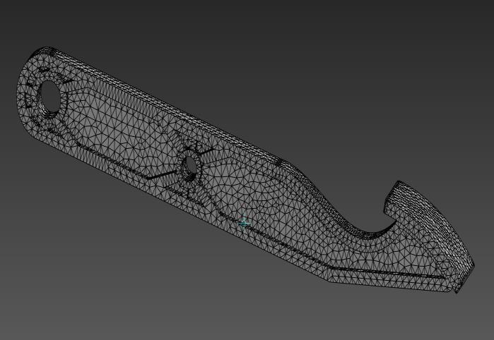
Fig-5:Brakepedalmodelmeshed.
InANSYS,userscaneitherchoosetheautomaticormanual way of meshing components; elements can be selected according to their shape and size. The pedal uses a configurationoftheTRIandHEXelementstoimprovethe stiffness,mainlyaroundthepivotanddistortedcurvature. Themeshingelementsizeisselectedas2mmforaprecise and high-quality simulation. This precise and fine-tuned approachmakessurethatthebrake'spedalisrepresentedin an actual way during numerical investigation. Through a smart combination of this presentation, engineers can achieve a high level of accuracy, since this technique simulatesreal-worldconditionsandacquiresperformance informationlikeelasticeffectsandstressdistribution.
4.4 Boundary conditions set for analysis.

Fig-6:Boundaryconditionsestablishedforprecise analysis.
The equation forthe total ofthe forces(F)that acton the brake pedal represents the maximum force that can arise andthatisestimatedtobe40kg.Theconversiontothelaw ofgravity(g)givestheresult:F=40*9.81=392.4N,which isequivalentto400N.Thenextpartistofind.


=0.12309MPa[1]
Besidesthat,thepivotpointofhalfofthepedalandthepush rod being attached to the master cylinder do not include drags.Thesereactiveforcesare,however,thoughttobeof negligibleproportionsinAl'sdesigndeliberations.
4.5 FEA Analysis of static structural behavior.
AnFEAstaticstructural analysisofa pedal isbasedonits equivalent Von Misses Stress and total deformation. The graphs consisting of both the research findings are presentedbelow.Wewillnowlookatthestrainprofilesofa selectedpedalunderstaticloadingconditions.Thiskindof analysishelpstodeterminethestructuralsafetyofthepart as well as deformation characteristics as a difference in cyclicandstaticloadingconditions.Thearistocracysuchas VonMissesTensionfiguresoutregionsthathavehigheffects of stress concentration, while pedal deflection with total deformationstandsforthepercentageofdeflectionofpedal under loads. Through the analysis of these dimensional characteristics, engineers try to keep the optimal pedal design in sight from the standpoint of safety and performance.Furthermore,graphicalrepresentationisfree of any extra confusion, aiding in easy comprehension and communicationoffindingstotechniciansandmanufacturers involvedinthedesignandthemanufacturingprocess.
Equivalent Von Mises stress in static structural analysis.

Fig-7:EquivalentVonMisesStress
The Von-Mises stress analysis yielded maximum and minimum equivalent stresses of 36.403 MPa and 0.0046 MPa,respectively.

International Research Journal of Engineering and Technology (IRJET) e-ISSN: 2395-0056
Volume: 11 Issue: 05 | May 2024 www.irjet.net p-ISSN: 2395-0072
Total Deformation in static structural analysis.
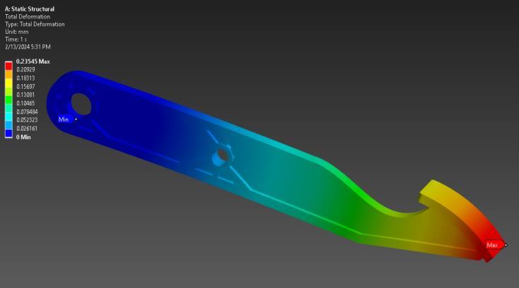
TotalDeformation
The total deformation analysis revealed maximum and minimum deformations of 0.23545 mm and 0 mm, respectively.
Safety Factor

Fig-9:SafetyFactor
SafetyFactorMax:15andMin:6.8676.
Flexiblebehavioralanalysis,whichisusuallyreferredtoas transientstructuralanalysis,isanessentialengineeringaid forstructuralbehaviorassessmentduringtime-dependent loads such as earthquakes. While the confines of static analysis revolve around how the structures behave being subjectedtoconstantstresses,transientstructuralanalysis exploreshowthedynamicresponsesarecausedbyvarying forcesovertime.Thispreciselyistheverybasicrequirement forgettingtoknowtheextentofhowstructuresbehavein naturalconditionswhereloadscanunexpectedlychangeor start fluctuating often. Through the approximation of dynamicloadingscenarios,thetransientstructuralanalysis willhelpengineersassesshowstructuresaregoingtoreact to forces, for instance; impact, vibration, or seismic
instability.Suchinformationshouldbeusedwhendesigning structures that are capable of resisting vagaries acutely induced events but at the same time ensuring both safety andreliability.
Overall, the impact of transient structural analysis is significant on the ergonomic behavior of structures; therefore,thisstudycouldbeusedindesign,optimization, and safety assessment across various engineering disciplines.FlexMLnotonlycangiveacompleteaccountof complexdynamicloadingconditionsbutitisalsoawidely usedtoolforthevalidationprocessofstructuralintegrityof engineeringsystemsindifferentapplications.
4.7 Analysis settings in brief Numberofsteps
Stepping
Timestep
Timestep
TimeIntegration on
s
Table2:Specificsregardinganalysisparametersprovided.
4.7 FEA results for transient structural
Equivalent Von Mises stress in transient structural
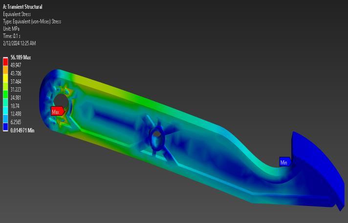
Fig-10:EquivalentVonMisesStressresult
The Von-Mises stress analysis yielded maximum and minimumequivalentstressesof56.189MPaand0.014971 MPa,respectively.

International Research Journal of Engineering and Technology (IRJET) e-ISSN: 2395-0056
Volume: 11 Issue: 05 | May 2024 www.irjet.net p-ISSN: 2395-0072

The total deformation analysis revealed maximum and minimum deformations of 0.33297 mm and 0 mm, respectively.
Topologyoptimizationstandsforacomputationtechnique utilized to design an optimized material placement in a chosendesignareatogetthebestmechanicalperformance under some set constraint positions. FEA (finite element analysis)isawell-knowncost-effectiveandhighlyholistic tool utilized in analyzing topology optimization studies. ANSYS provides an entire complex analysis platform that coversmanysimulationtypesandletsengineersinvestigate manydesignoptionsandanalyzetheirresponsesunderthe different conditions of loading. Humanize: ANSYS for topology optimization allows engineers to quantumly go through their design iteration process because of the capacityofthesoftwaretoautomaticallyadjustthematerial distribution inside the given design domain to meet performanceconstraintswhilesatisfyingdesignconstraints inthesameway.TheengineofANSYStopologyoptimization ofthedesigningprocessentailsthecreationofdesignspace, defining boundary conditions, imparting the loading conditions,definingthematerialproperties,andcreatingthe optimization objectives. Subsequently, ANSYS implements advancedalgorithmsthatrecursivelyallocatematerialtothe design space, and this is a process that seeks the best material configuration that reduces the mass without sacrificingstructuralintegrityandalsoachievesthedesign performance requirements. In this repetitious procedure, engineerscaninvestigateabroadrangeofpotentiallayouts and reveal very original solutions that usually would not havebeenidentifiedthroughconventionaldesignmethods. Foradditionalcontribution,thereareANSYS’visualization toolswhichareadvancedenoughtogiveengineersachance toanalyzeandinterpretthetopologyoptimizationresults effectively. Engineers apply various stress distribution, displacement patterns, and other performance metrics to haveaviewofthedynamicperformanceofthesystemwith enhanceddesign.Asaresult,theexpertscanmaketheright
decisionsandimprovethedetailsofthedesignstepbystep sothatthefinalresultisclosetothedesiredachievement.
Using the layer-by-layer zone designation allocated to the design, the tool inside the ANSYS software for topology optimization took over and produced the optimized free formintheproduct.Theprocessistoachieveaconsiderable weightreduction,usuallyfindingthattheoptimizedmodel typicallypresentsa50%reductioncomparedtoitsoriginal counterpart.

Frontviewdisplaying50%massoptimization.
The defining of the regions within the design space is an integralpartoftopologyoptimizationbecauseitdecidesthe locationwherematerial redesigningtakesplace toreduce weightasmuchasnecessaryforthestructuretomaintainits integrityandfunction.Providedtheregionsareassigned,a topologyoptimizationalgorithmistheniterativelyapplied between these regions to redistribute the material to accomplish the stated objectives, such as mass reduction giventhatperformancecriteriaaremet.Throughapplying varioustechniquessuchasletdown,brushing,andfilling, the optimized model free form now stands to be the final design of the configuration that conforms to the predetermined functions. Therefore, the model aims to achieve such features as enhanced structural efficiency, decreased mass, and superb performance. Through the deployment of ANSYS software's advanced topology optimizationprocess,itiseasytosearchandlocatethemost suitabledesignlayoutwhichpossessesthegreatestweightsaving advantages but does not compromise the system's structuralintegrityorfunctionality.


International Research Journal of Engineering and Technology (IRJET) e-ISSN: 2395-0056
Volume: 11 Issue: 05 | May 2024 www.irjet.net p-ISSN: 2395-0072
Thisrecurringprocessofdesignatingregions,executingthe topologyalgorithmonthespecifiedarea,andanalyzingthe freeformoftheoptimizedportioncontinuouslyenablesthe engineerstorefineandenhancethedesignuntilthesetlightweightingandperformanceobjectivesarereached.Tosum up, topology optimization, using ANSYS software, offers engineers in different industries such as automotive, aerospace, and manufacturingan extremelypowerful tool for a dual purpose: on the one hand, they can achieve the “optimalstructure”ofcomponentsandontheotherhand, theycandeploythesuggesteddesignsintoreality.
In SolidWorks software, topology optimization starts by setting the zones or sections of the area where the main structurewillactasthecontrolleroftheoveralldesign.After that,thetopologytoolwillruntogettheoptimizedmodelin freeform.Thisprocessinvolvesthe penetrationof coated materiallayersthatdelivermajorweightreductionto60% to80%weightoftheoriginalcomponent.

Theutilizationofzoneswithinthestudyspaceisasalient functionofthetopologyoptimizationasitcontrolstheparts to which material reduction is affluent in the sense of the weightreductiontensilestrengthandperformance.Thisis then followed by the regions being distributed. Subsequently, total volume redistribution via SolidWorks throughout those regions is accomplished repetitively to ensure that the specific goals are satisfied, such as having lessmasswhileretainingperformance.

Thefreeformofthefinaloptimizedmodelstandingforthe result of its optimization process that fulfills the optimizationgoalshasbeenchangedtomeetthetargetsthat were set at its beginning. This model which utilizes structural efficiencies, saved mass and increased performanceisreferredtoasanoptimizedmodel.Thisisa development from the initial product. By using the SolidWorks software capacity in spending on topology optimization,theengineerscantherebyrapidlyexploreand recognizehigh-weightsavingsdemarchesthatdonotmake compromisesofeitherstructuralintegrityorfunctionality.

The iterative process of sectioning, running the topology slots, and analyzing the free-form analysis model which showstheoptimizedshapesthatcanbeachievedenablesthe engineerstoiterativelyrefineandimprovethedesignsuntil thedesiredmassreductionandperformancegoalsaremet. Summing up, topology optimization with SolidWorks software is a very potent tool for engineers to realize the best and most effective imaginable designs which, due to makingthecomponentslighter,leadstosubstantialsavings ofweightofthecomponentacrossdifferentindustrialareas, suchasautomotive,aerospaceandmanufacturing.
6. The Optimized ModelUnderwent a Redesign and FEA Analysis.


International Research Journal of Engineering and Technology (IRJET) e-ISSN: 2395-0056
Volume: 11 Issue: 05 | May 2024 www.irjet.net p-ISSN: 2395-0072
Inallcases,experimentsareundertakentoensureidentical conditionsaremaintainedforbothoptimizedandoriginal brake pedals. The tension of 0.12309 MPa is applied to a particularmodeluntilitbreaksatthefreeendwhilebeing fixedathehingedend.Testinghasstaticanddynamictypes of loads comprising scenarios. Stress or deformation is measuredasthedifferencebetweenthestressresultofthe deformedandUndeformedpedal.Thisprocedureinvolves thesimulationsinvolvingtheoptimizeddesignswhichmust withstandthesameoperationalenvironmentastheoriginal pedal to ensure that the design parameters have been successfully validated. Through comparative stress-strain analysis of the expected outcomes and the original part, engineers discover whether the improved design has the samefunctionalityandsafetycharacteristicsastheoriginal one under intense field testing. Such extensive analysis ensures that the optimized models recommended for real useinautomotivesystemsarerobustandadequate,which empowers the systems to deliver effective services and performatahighstandard.
6.2 Equivalent Von Mises stress in static structural analysis.

Fig-18:EquivalentVonMisesStressresult
The Von-Mises stress analysis yielded maximum and minimumequivalentstressesof32.776MPaand0.0017842 MPa,respectively.
6.3 Total Deformation in Static Structural Analysis.
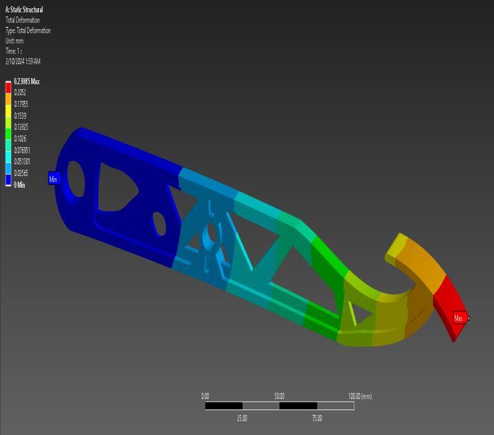
Fig-19:Deformationresults
Thetotaldeformationanalysisrevealedmaximumand minimumdeformationsof0.23085mmand0mm, respectively.
6.4 Safety Factor
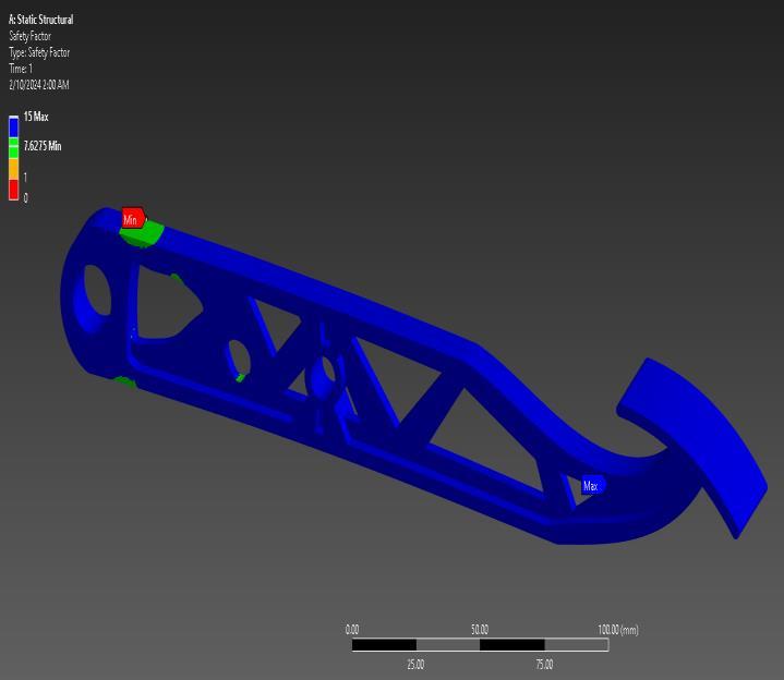
Fig-20:SafetyFactor SafetyFactorMax:15andMin:7.6275.

International Research Journal of Engineering and Technology (IRJET) e-ISSN: 2395-0056
Volume: 11 Issue: 05 | May 2024 www.irjet.net p-ISSN: 2395-0072
6.5 Transient Structural Analysis of Optimized Model1
Equivalent Von Mises stress in transient structural
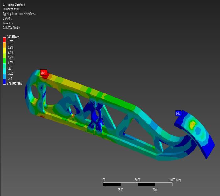
Fig-21:EquivalentVonMisesStressresult
TheVon-Misesstressanalysisyieldedmaximumand minimumequivalentstressesof24.747MPaand 0.0015527MPa,respectively.
Total Deformation in transient structural Analysis.

Fig-22:Deformationresults
The total deformation analysis revealed maximum and minimum deformations of 0.18251 mm and 0 mm, respectively.
Details on Optimized Model -2 (0.54716 kg)

Fig-23:Model-2(0.54716kg)
6.2.1 Static Structural Analysis of Optimized Model-2
EquivalentVonMisesstressinstaticstructuralanalysis.
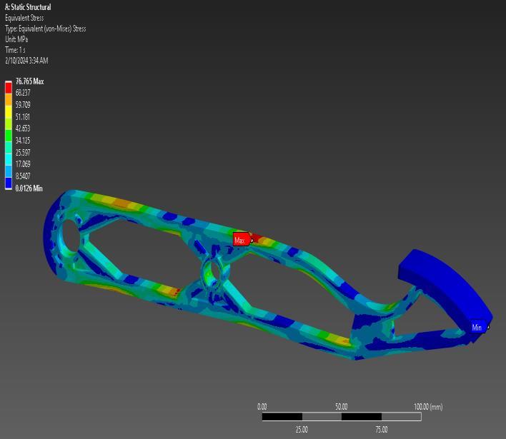
Fig-24:EquivalentVonMisesStressresult
The Von-Mises stress analysis yielded maximum and minimum equivalent stresses of 76.765 MPa and 0.0126 MPa,respectively.

International Research Journal of Engineering and Technology (IRJET) e-ISSN: 2395-0056
Volume: 11 Issue: 05 | May 2024 www.irjet.net p-ISSN: 2395-0072
Total Deformation in static structural analysis.
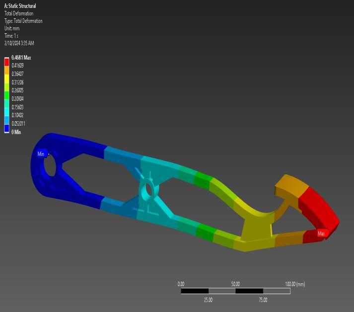
Fig-25:Deformationresults
The total deformation analysis revealed maximum and minimum deformations of 0.4681 mm and 0 mm, respectively.
6.2.2 Safety Factor

Fig-26:SafetyFactor
SafetyFactorMax:15andMin:3.2567.
6.2.3 Transient Structural Analysis of Optimized Model-2
Equivalent Von Mises stress in transient structural

Fig-27:EquivalentVonMisesStressresult
The Von-Mises stress analysis yielded maximum and minimumequivalentstressesof157.32MPaand0.022055 MPa,respectively.
6.2.4 Total Deformation in transient structural Analysis.

Fig-28:Deformationresults
The total deformation analysis revealed maximum and minimum deformations of 0.90623 mm and 0 mm, respectively.

International Research Journal of Engineering and Technology (IRJET) e-ISSN: 2395-0056
Volume: 11 Issue: 05 | May 2024 www.irjet.net p-ISSN: 2395-0072
Details on Optimized Model -3 (0.562 kg)

Fig-29:Model-3(0.562kg)
6.3.1 Static Structural Analysis of Optimized Model-3
Equivalent Von Mises stress in static structural analysis.
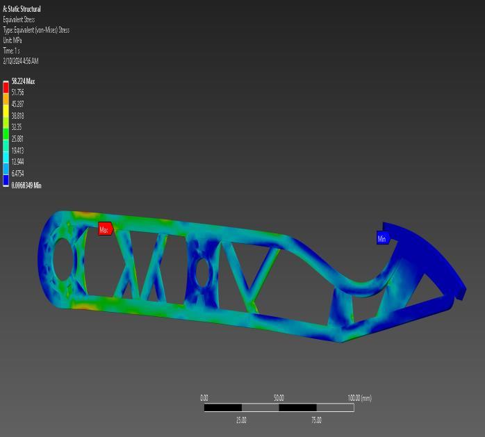
Fig-30:EquivalentVonMisesStressresult
The Von-Mises stress analysis yielded maximum and minimum equivalent stresses of 58.224 MPa and 0.0068 MPa,respectively.
Total Deformation in static structural analysis.
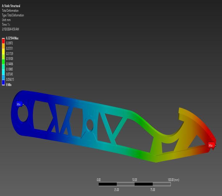
Fig-31: Deformation results total deformation analysis revealedmaximumandminimumdeformationsof0.32594 mmand0mm,respectively.
6.3.2 Safety Factor

Fig-32:SafetyFactor SafetyFactorMax:15andMin:4.2937.
© 2024, IRJET | Impact Factor value: 8.226 | ISO 9001:2008

International Research Journal of Engineering and Technology (IRJET) e-ISSN: 2395-0056
Volume: 11 Issue: 05 | May 2024 www.irjet.net p-ISSN: 2395-0072
6.3.3 Transient Structural Analysis of Optimized Model3
Equivalent Von Mises stress in transient structural

Fig-33:EquivalentVonMisesStressresult
The Von-Mises stress analysis yielded maximum and minimumequivalentstressesof85.476MPaand0.0057042 MPa,respectively.
Total Deformation in transient structural Analysis.

Fig-34:Deformationresults
The total deformation analysis revealed maximum and minimum deformations of 0.45939 mm and 0 mm, respectively.
Details on Optimized Model - 4 (0.53694 kg)
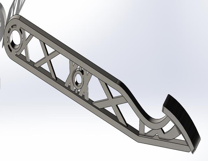
Fig-35:Model–4(0.53694kg)
6.4.1 Static Structural Analysis of Optimized Model- 4
Equivalent Von Mises stress in static structural analysis.
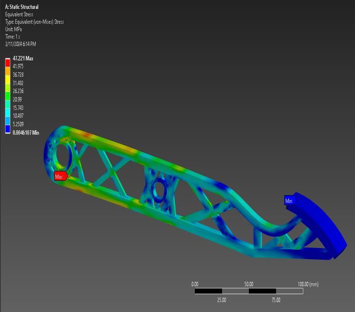
Fig-36:EquivalentVonMisesStressresult
The Von-Mises stress analysis yielded maximum and minimumequivalentstressesof47.221MPaand0.0046107 MPa,respectively.

International Research Journal of Engineering and Technology (IRJET) e-ISSN: 2395-0056
Volume: 11 Issue: 05 | May 2024 www.irjet.net p-ISSN: 2395-0072
Total Deformation in static structural analysis.
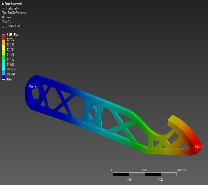
Fig-37:Deformationresults
The total deformation analysis revealed maximum and minimum deformations of 0.3181 mm and 0 mm, respectively.
6.4.2 Safety Factor

Fig-38:SafetyFactor
SafetyFactorMax:15andMin:5.2943.
6.4.3 Transient Structural Analysis of Optimized Model-4
Equivalent Von Mises stress in transient structural

Fig-39:EquivalentVonMisesStressresult
The Von-Mises stress analysis yielded maximum and minimumequivalentstressesof91.519MPaand0.0078567 MPa,respectively.
Total Deformation in transient structural Analysis.

Fig-40:Deformationresults
The total deformation analysis revealed maximum and minimum deformations of 0.61698 mm and 0 mm, respectively.

International Research Journal of Engineering and Technology (IRJET) e-ISSN: 2395-0056
Volume: 11 Issue: 05 | May 2024 www.irjet.net p-ISSN: 2395-0072
Details on Optimized Model -5 (0.54843 Kg)

Fig-41:Model–5(0.54843kg)
6.5 Static Structural Analysis of Optimized Model-5
Equivalent Von Mises stress in static structural analysis.

Fig-42:EquivalentVonMisesStressresult
The Von-Mises stress analysis yielded maximum and minimumequivalentstressesof47.224MPaand0.0047354 MPa,respectively.
Total Deformation in static structural analysis.

Fig-43:Deformationresults
The total deformation analysis revealed maximum and minimum deformations of 0.31672 mm and 0 mm, respectively.
6.5.1 Safety Factor
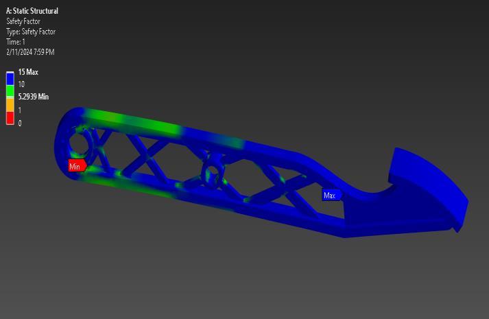
Fig-44:SafetyFactor
SafetyFactorMax:15andMin:5.2939.
© 2024, IRJET | Impact Factor value: 8.226 | ISO 9001:2008

International Research Journal of Engineering and Technology (IRJET) e-ISSN: 2395-0056
Volume: 11 Issue: 05 | May 2024 www.irjet.net p-ISSN: 2395-0072
6.5.2 Transient Structural Analysis of Optimized Model5
Equivalent Von Mises stress in transient structural

Fig-45:EquivalentVonMisesStressresult
The Von-Mises stress analysis yielded maximum and minimumequivalentstressesof89.149MPaand0.004439 MPa,respectively.
6.5.3 Total Deformation in transient structural Analysis.

Fig-46:Deformationresults
The total deformation analysis revealed maximum and minimum deformations of 0.59876 mm and 0 mm, respectively.
Details on Optimized Model - 6 (0.57803kg)

Fig-47:Model–6(0.57803kg)
6.6 Static Structural Analysis of Optimized Model - 6
Equivalent Von Mises stress in static structural analysis.

Fig-48:EquivalentVonMisesStressresult
The Von-Mises stress analysis yielded maximum and minimumequivalentstressesof47.884MPaand0.0074918 MPa,respectively.

International Research Journal of Engineering and Technology (IRJET) e-ISSN: 2395-0056
Volume: 11 Issue: 05 | May 2024 www.irjet.net p-ISSN: 2395-0072
Total Deformation in static structural analysis.

Fig-49:Deformationresults
The total deformation analysis revealed maximum and minimum deformations of 0.29485 mm and 0 mm, respectively.
6.6.1 Safety Factor

Fig-50:SafetyFactor SafetyFactorMax:15andMin:5.2209.
6.6.2 Transient Structural Analysis of Optimized Model-6
Equivalent Von Mises stress in transient structural
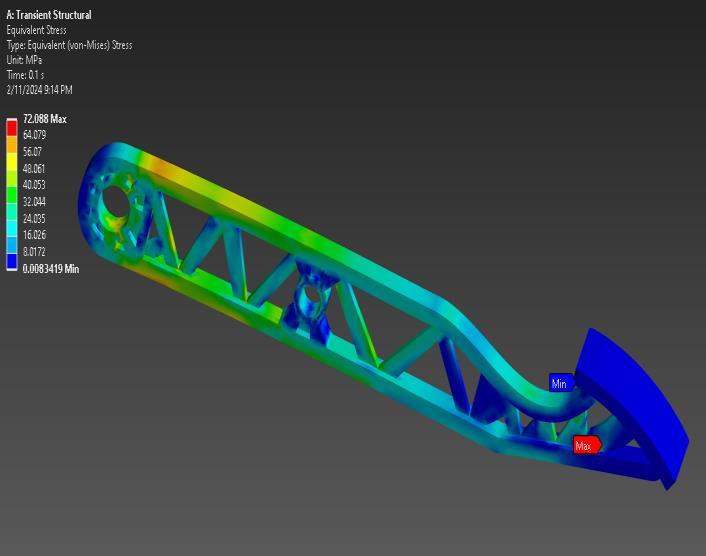
Fig-51:EquivalentVonMisesStressresult
The Von-Mises stress analysis yielded maximum and minimumequivalentstressesof72.088MPaand0.0083419 MPa,respectively.
Total Deformation in transient structural Analysis.

Fig-52:Deformationresults
The total deformation analysis revealed maximum and minimum deformations of 0.46531 mm and 0 mm, respectively.

Volume: 11 Issue: 05 | May 2024 www.irjet.net
7. Results and Discussion
Table-3: Von Misses stresses (MPa)
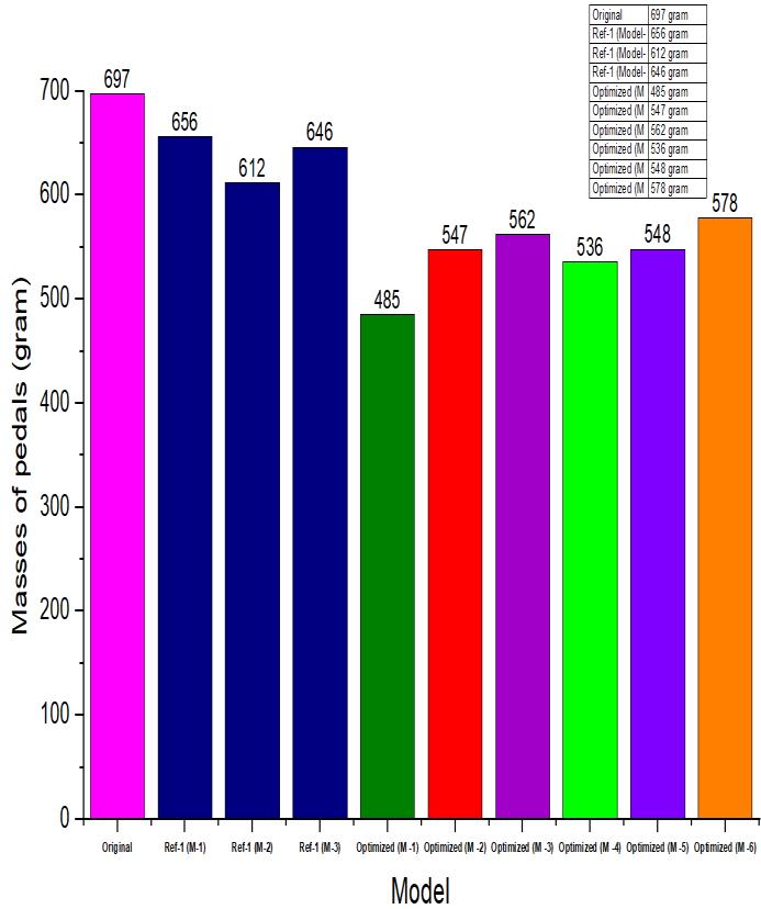
Table 5: Masses of pedals (gm)
Table 4: Total deformation (mm)

International Research Journal of Engineering and Technology (IRJET) e-ISSN: 2395-0056
Volume: 11 Issue: 05 | May 2024 www.irjet.net p-ISSN: 2395-0072
-6: Safety Factor

Graph2:AlloftheoptimizationmodelsafetyfactorsGraph
In this study, the original brake pedal has a mass of 697 grams,InReferencemodels1,2,3achievesweightsavingsof 41,85 and 51 grams, respectively. on the contrary, The optimized model presented in this paper (model 1- 6) demonstrates significantly greater weight saving, with savingof212,150,135,161,149,and119gramsrespectively. As a result, the safety factor of the original model is calculatedtobe6.8676.Uponoptimization,wecanmeasure the safety factor for model 1 as 7.6275, for model 2 as 3.2567,formodel 3as4.2937,formodel 4as5.2943,and model5as5.2939,formodel6,and5.2209,respectively.The safety criteria revealed that the models passed all of the limitations and demonstrated a topology optimization processthatincreasedthesafety ofthepedalofthebrake while decreasing the weight simultaneously, which highlights the effectiveness of the topology optimization approachinimprovingbothweightandsafetyperformance ofthebrakepedal.
Finally,itcanbesaidthatthepapershowsitsefficiencyas beingappliedtoweightreductionofbrakepedalbynotonly improving but keeping up the efficiency. Through the optimization process, substantial weight savings were achievedincomparisontoreferencemodels,withreductions rangingfrom119to212gramsacrosssixoptimizedmodels. On top of this, the safety factors of all optimized models beingcheckedwiththesafetystandardsaffirmthedesign andabilityofthebrakepedaltosustainandwithstandhigh
loads and impact. The results in question, thus, verify the efficacyoftopologyoptimizationinimpartingthenextidea ofincreasingtheefficiencyandperformanceofautomotive parts. Such optimization processes by engineers with the help of advanced optimization methods can make brake pedalslightweightbuttoughenoughtobeefficientforthe whole improved vehicle efficiency and safety. The paper above,therefore,demonstratestheroleplayedbytopology optimization in the design and optimum configuration of automotivecomponents,anditunveilsthepossibleavenues of development in lightweight and high-performance automotivecomponentsforfuturepurposes.
1. Kharde, A., et al., Design and mass optimization of brake pedal using topology optimization technique. InternationalResearchJournalofEngineeringand Technology(IRJET),2021. 8:p.2395-0056.
2. Piekło, J., S. Pysz, and M. Małysza, Zastosowanie optymalizacji topologicznej w kształtowaniu odlewanych konstrukcji szkieletowych. Prace InstytutuOdlewnictwa,2014. 54
3. Doğan,O.,etal., Optimum Design of Brake Pedal for Trucks Using Structural Optimization and Design of Experiment Techniques. International Journal of AutomotiveScienceAndTechnology,2020. 4(4):p. 272-280.
4. Akçay,Ö., StructuralOptimizationoftheBrakePedal usingArtificialIntelligence. InternationalJournalof AutomotiveScienceAndTechnology,2023. 7(3):p. 187-195.
5. Salit,M.S.,etal., Conceptual designofanautomotive composite brake pedal Suranaree J. Sci. Technol, 2005. 12(3):p.173-177.
6. Dhande, K., N. Jamadar, and S. Ghatge, Design and analysis of composite brake pedal: an ergonomic approach. IntJMechEngRobotRes,2014. 3(3):p. 474-482.
7. GAWANDE, M.A.N., G. KONDHALKAR, and A.R. PAWAR, STATIC STRUCTURAL ANALYSIS AND OPTIMIZATION OF BRAKE PEDAL. 2017.
8. Ergenc,A.F.,etal., Reducedweightautomotivebrake pedal test & analysis. International Journal of AutomotiveScienceandTechnology,2017. 1(2):p. 8-13.
9. Kaya,N.,I.Karen,andF.Öztürk, Re-designofafailed clutchforkusingtopologyandshapeoptimisationby the response surface method. Materials & Design, 2010. 31(6):p.3008-3014.

International Research Journal of Engineering and Technology (IRJET) e-ISSN: 2395-0056
Volume: 11 Issue: 05 | May 2024 www.irjet.net p-ISSN: 2395-0072
10. Cavazzuti, M., et al., High performance automotive chassis design: a topology optimization based approach. Structural and Multidisciplinary Optimization,2011. 44:p.45-56.
11. Chang, J.W. and Y.S. Lee, Topology optimization of compressor bracket. Journalofmechanicalscience andtechnology,2008. 22:p.1668-1676.
12. Sudin, M.N., et al., Topology optimization in automotive brake pedal redesign. International JournalofEngineeringandTechnology(IJET),2014. 6(1):p.398-402.
13. Romero, J. and N. Queipo, Reliability-based and deterministic design optimization of a FSAE brake pedal: a risk allocation analysis. Structural and multidisciplinary optimization, 2017. 56: p. 681695.
14. Das,S., Designandweightoptimizationofaluminum alloy wheel. International Journal ofScientificand ResearchPublications,2014. 4(6):p.1-12.
15. Yadav,P.andP.Ramadasi, Optimization of car rim using Optistruct. J.Environmental Sci.,Toxicology, andFoodTech,2012. 2(3):p.10-15.
16. Xiao, D., et al., Novel steel wheel design based on multi-objective topology optimization. Journal of Mechanical Science and Technology, 2014. 28: p. 1007-1016.
17. Kumar,C.P.R.andR.S.Meher, Topologyoptimization of aluminium alloy wheel. International Journal of Modern Engineering Research, 2013. 3: p. 15481553.
18. Ragul, G., et al., Design, Analysis And Impact Behaviour Of Magnesium Alloys (Zk60a) Of Low Pressure Die Casting For Automotive Wheels By Finite Element Method. 2006.
19. Kulangara, A.J., C. Rao, and J. Cherian, Topology optimization of lattice structure on a brake pedal. Materials Today: Proceedings, 2021. 47: p. 53345337.
20. Sargini, M., et al., Additive manufacturing of an automotive brake pedal by metal fused deposition modelling. MaterialsToday:Proceedings,2021. 45: p.4601-4605.


RUYHAN
Master'sStudent
School ofMechanicalEngineering
Xi'anJiaoTongUniversity
Xi'an,China
AbdullahAlHossainNewaz Master'sStudent School of MechanicalEngineering UniversityofBridgeport,USA
MdMehediHassanMelon
Master'sStudent DepartmentofBusiness Administration, InternationalAmerican UniversityLosAngeles,USA