
International Research Journal of Engineering and Technology (IRJET) e-ISSN: 2395-0056
Volume: 11 Issue: 05 | May 2024 www.irjet.net p-ISSN: 2395-0072
International Research Journal of Engineering and Technology (IRJET) e-ISSN: 2395-0056
Volume: 11 Issue: 05 | May 2024 www.irjet.net p-ISSN: 2395-0072
Om Rajkumar Solavat1
1K.J. Somaiya College of Engineering, Somaiya Vidyavihar University, Mumbai, Maharashtra
2Professor Vaibhav Narwane, Dept. of Mechanical Engineering, Somaiya Vidyavihar University, Mumbai, Maharashtra ***
Abstract - This project aims to design and fabricate a mobile robot that can follow the path with the help of IR Sensors. Path following proves to be very useful in today’s moderntechnologyandit is stillconsideredanimportantfield of robotics. This type of robot is based on decision-making algorithms. The main aim of this project is to make an Arduino-based efficient self-directed path-following robot. A simple path-following algorithm “LSRB algorithm” is used to make this robot. In this project, Hardware development, software development, andpath constructionhavebeendone. For capability testing, the robot will implement to follow the black path and complete the maze.
Key Words: Autonomous Mobile Robot, Arduino, LSRB Algorithm, Decision -making algorithm, Path Follower Robot, IR Sensor
PathplanninginAutonomousMobileRobotNavigationisan important part of the robotics field. Autonomous Mobile Robots(AMRs)canbedefinedasroboticsystemsthatare able to navigate without disruption and no human intervention in their movement, to avoid obstacles and followapredefinedpath(1).ThedemandforAMRsisrising to its peak across various applications such as logistics transportation (2), robotic cleaning services (7), and surveillanceforvariouspurposes.Thistypeofrobotcanalso become a boon in the agriculture field if it is properly designed for unpredictable agricultural climates solving many problems for humans like labor shortages, natural phenomena,andeconomicissues (3)
AMRsusuallynavigatethroughagloballydefinedgeometric path with loose time constraints and can be divided into controltheory-basedmethodsandgeometricmethods(5). Control theory-based methods, such as Proportional–Integral–Derivative (PID) controllers, face challenges in finding optimal parameters (4). Geometric methods, compared to control theory-based methods, have become more popular due to their simplicity, robustness, and suitability for real-time control. The Pure Pursuit (PP) controller,proposedastheearliestgeometricapproachfor path following, fits a circle through the vehicle’s current positiontoapointonthepathaheadofthevehiclebyalookaheaddistance (5)
Path-follower robots are used in industry to transport materials and objects autonomously by following a particularpath,whichmaybedrawnlinesormagnetictapes on the floor that are detected by a sensor array. High performance,highaccuracy,lowerlaborcost,andtheability to work in hazardous places have put robotics in an importantpositionovermanyothersuchtechnologies (6) Inthispaperpathfollowingrobothasbeenpresentedwhich willtraceablackpathonawhitesurfacewiththehelpofIR Sensors, Arduino Board microcontroller, L298N Motor Driver, etc. AMRs follow the LSRB Algorithm, which is usually used in this type of robot. Therefore, this kind of Robot should sense the line with its Infrared Ray (IR) sensors installed under the robot. After that, the data is transmitted to the processor by specific transition buses. Hence, the processor is going to decide the proper commandsandthenitsendsthemtothedriverandthusthe pathwillbefollowedbythelinefollowerrobot
Bhargav Srinivasan and S. Siva Sathya propose a genetic algorithm-basedapproachformazesolvingusingamobile robot. Ajith Abraham and Crina Grosan propose a hybrid approach,whichcombinesageneticalgorithmwithafuzzy logic controller to generate an optimal path through the maze.H.N.KrishnanandK.K.Gowtham(2018)builtarobot whose movements are controlled by an Arduino microcontroller, which receives input from the image processingalgorithm.
Inthemiddleofthe20thcentury,Path-followingproblems become an essential field of robotics. In the year of 1972, editors of IEEE Spectrum magazine came up with the conceptofamicro-mousewhichisasmallmicroprocessorcontrolled vehicle with self-intelligence and capability to navigateacriticalpath. TheninMay1977,thefastUSMicro mousecontest,called“AmazingMicromouseMazeContest” wasannouncedbyIEEESpectrum.Fromthen,thistypeof contest became more popular, and many types of mazesolvingrobotsaredevelopedeveryyear.Inthelate1970s, the designs ofthe path-solving robots’ designs were used tohavehugephysicalshapesthatcontainedmanyblocksof logicgates.
International Research Journal of Engineering and Technology (IRJET) e-ISSN: 2395-0056
Volume: 11 Issue: 05 | May 2024 www.irjet.net p-ISSN: 2395-0072
Thegoal oftheprojectis tobuilda microcontroller-based system that is the brain of the robot, it is used to collect informationfromvariousinputdevicessuchassensorsto followthepath,byachievingthefollowingobjectives:
1-Designasmall-scalerobotthatcanfollowthepathand solveit.
2-Assemblethehardwarecomponentslikesensors,motor driver,andMicrocontroller
3-Converttheapprovedalgorithmintoacodetocontrol therobot.
4-Makearequiredpath.
5-CapturingthelinepositionwithIRsensorsmountedat thefrontendoftherobot
Path Follower Robot
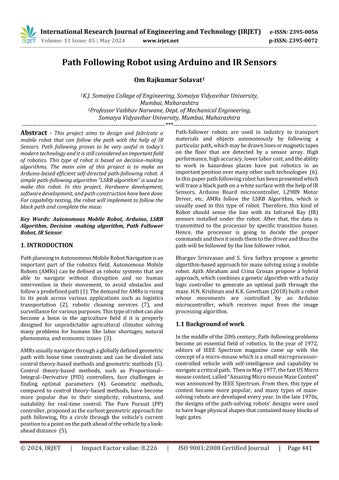
2.1 Block Diagram
Initially, I chose a configuration to build a path follower usingfourInfraredSensors(Althoughonly2IRSensorsare shownintheblockdiagram)withaconnectionofanArduino UnomicrocontrollerthroughanL298NMotorDriver.Below istheblockdiagramwhichwas followedasareference in themakingoftherobot.Itillustratestheconnectionforthe developmentofthelinefollowerwhichfollowsablackpath onawhitesurface.
2.2 Components used
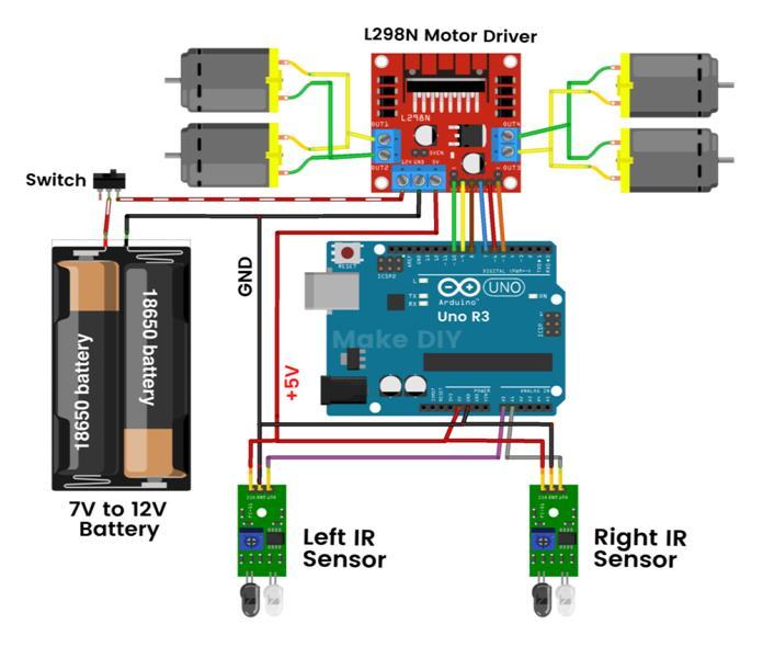
1) 4WD Car kit
Kitcontains12voltsDCmotors,Wheels,NutsandScrews, chassis,andjumperwires.
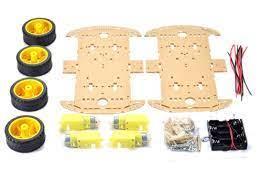
2) L298N Motor Driver
TheL298NisadualH-Bridgemotordriverthatcontrolsthe speed and direction of DC motors. Four DC motors were connectedtoL298N,twoontherightsideandtwoontheleft side. The module can drive DC motors that have voltages between5and35V,withapeakcurrentofupto2A.
International Research Journal of Engineering and Technology (IRJET) e-ISSN: 2395-0056
Volume: 11 Issue: 05 | May 2024 www.irjet.net p-ISSN: 2395-0072
3) Arduino Uno
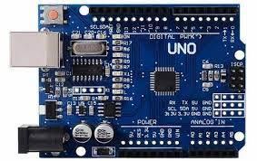
-4:ArduinoUnoBoard(Microcontroller)
• Processor-ATMEG328P
• InputVoltage-5V/7-12V
• SpeedofUSB-16MHz
• DigitalI/Opins-14(6PWN)
• AnalogI/OPins-8
Arduino is an open-source platform used for building electronics projects. Arduino consists of both a physical programmablecircuitboardand anIDEthatrunsonyour computer,usedtowriteanduploadcomputercodeto the physicalboard.TheArduinoIDEusesasimplifiedversionof C++,makingiteasiertolearntoprogram.
4) IR Sensors
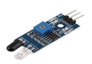
Fig -5:InfraredSensor
Mainchip–LM393
OperatingVoltage–3.6/5V
Effectivemeasuringrange–2cmto80cm
InfraredSensorsareutilizedtofindoutthepositionofthe path with respect to the position of the robot. The White surface of the path reflects the light and the black path
receivesitafterthetransmission.Thereare4IRSensors,1 totheright,1totheleft,and2inthemiddle.RightandLeft IR Sensorswill runoverthe whitesurfaceandthemiddle sensorswillrunovertheblackpath.Thiswillhelptherobot tofollowtheblackpathinastraightmotion.
Inthiscondition,asufficientamountoflightgetsreflected back to the LDRs. So, their resistance will be low. So, the voltagedroppedacrosstheLDRwillbelow.Whentherobot driftstooneside,thesensorontheoppositesidefallsover theblacklineandtheintensityoflightreflectedbacktothe correspondingLDRwillbelow.Asaresult,theresistanceof theLDRshootsupandthevoltagedroppedacrossitwillbe high. The voltages dropped across the right and left LDRs (nodes marked R and L in the above circuit) are given as input to the analog input pins A3 and A4 of the Arduino board.ThesesensorsareconnectedtotheChassisandthen usedforoursystem.
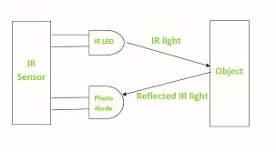
Path Following robot is very similar to the Line Follower Robot. In this project, sensors are used to detect the path rather than sensing the light. Hence any kind of lightsensitive sensor could be used for the robot to follow the path.SoInfraredraysensorwillfirstsendawavelengthfor detectingablackpathandthenotherinfraredraysensors willbereceivingtheinformationandmakethedecisionto followablackpathonawhitesurface.
Inthisway,Sensorsattachedinthefrontofthechassisgive signalstothemicrocontroller.Themicrocontrollerreceives thisinputfromtheIRSensors,processesitaccordingtothe programmingdoneintheArduino,andgivesthesignalsto theMotordriver.MotordriverL298N,accordingtotheinput received from the Arduino, controls the DC motors. This entiremechanismresultsintherobotfollowingthepathand reaching its end. “LSRB Algorithm” is used for the programmingoftherobot.
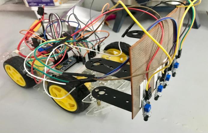
Therobotbody(chassis)isthree-layered.Itismadeoflasercutfiberglass.ArduinonanoandL298Nmotordriversare placed on the chassis. 4 DC motors with the 4 wheels are attachedtothechassis. ConnectionsfromL298NtoArduino andArduinotoIRSensorsaremadeusingbreadboard.The 12VBatteryisconnectedtotheL298Nmotordriver
Volume: 11 Issue: 05 | May 2024 www.irjet.net p-ISSN: 2395-0072
4. LSRB Algorithm
Thisisthealgorithmbywhichtherobotfollowsthepath.In "LSRB",Lstandsfor'LEFT',Sfor'STRAIGHT',Rfor‘RIGHT’ , and B for 'BACK' or BACKWARD. These LEFT, RIGHT, STRAIGHT, and BACK are the directions that the robot follows.Inthisalgorithm,theLEFTdirectionhasthehighest priority and the BACK (U-Turn) direction has the least priority.Let'sseewhatthisalgorithmlookslike:
• Step 1: Always follow LEFT whenever there is a turn possible7.
• Step2:IfLEFTisnotpossible,goSTRAIGHT.
• Step 3: If LEFT and STRAIGHT both are not possible, takeRIGHT.
• Step4:ifLEFT,STRAIGHT,andRIGHTarenotpossible, goBACK(oritmeans,takeaU-Turn)
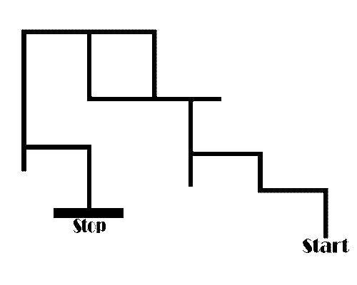
TherobotsolvesthePath.Becauseofthefrontsensorrobot movesforwardandbecauseoftheleftandrightsensorsit takes the required turns. The robot follows the LSRB AlgorithmtotraveltillthePathends.Thistypeofrobotcan also be made by using ultrasonic sensors that detect obstaclesandsolvethepath.TheTimeRequiredbythecar tocoveradistanceof60cmpathisapprox.4sec Thespeed ofthecarisapprox.15cm/sor220RPM.IRSensorsdetect the path in the range of 2cm-80cm by increasing or decreasingitssensitivity. TheRobotrunsontheBlackpath of the maze using IR Sensors. IR sensors give output as 0 whenitdetectsablackpath/noobjectand1whenitdetects a white path/object. Arduino UNO Board (which acts as a micro-controller) takes input from Infrared Sensors and transfersoutputintotheL298Motordriver,whichcontrols all the DC motors according to the program. This whole systemconnectedAltogetherworksasaPathSolvingRobot.
Nowadays, robots are widely used in various critical and dangerous finds.Thisprojectisbasedondecision-making algorithms.So,itcanbeusedinvariousintelligencefields.It can be used for rescue operations, navigation problems, search operations, medical attention, military search and rescue,etc.Therearemanycaves,thatarelikemazeswhere humanscouldgetlost.Thisrobotcanfinditswayoutagain. Itcanalso beusedintoosmall ordangerous caveswhere humanscan’tenter.High-performancesensorscanbeused byus for the better-performancerobot.Insteadofusinga path,wemayaddanultrasonicsensortolettherobotmove inthenaturalenvironmentbyavoidinganyobstacleitmay face while moving. We can add PID control to make our functionwellbymanagingthespeedofourmotorwhichis donebycalculatingtheerrorvalue.
1.Areviewonchallengesofautonomousmobilerobotand sensor fusion methods. Alatise, M.B. and Hancke, G.P. Akure,Nigeria:IEEE,2020,Vol.8.
2.Amaster-slaveseparateparallelintelligentmobilerobot usedforautonomouspallettransportation.. Li, G., et al. 3, s.l.:Appliedsciences,2019,Vol.9.
3. A review of autonomous agricultural vehicles. Roshanianfard, A., et al. Hokkaido:J.Terramech,2020,Vol. 91,pp.155-183.
4. Design of a control system for an autonomous vehicle basedonadaptive-pid. Zhao, P., et al. s.l.:Int.J.Adv.Robot. Syst.,2012,Vol.9,p.44.
International Research Journal of Engineering and Technology (IRJET) e-ISSN: 2395-0056
Volume: 11 Issue: 05 | May 2024 www.irjet.net p-ISSN: 2395-0072
5.CF-pursuit:Apursuitmethodwithaclothoidfittinganda fuzzycontrollerforautonomousvehicles. Shan, Y., et al. s.l.: Int.J.Adv.Robot.Syst.,2015,Vol.12,p.134.
6. Line Follower Using Arduino And Its Applications. Md Younus, Pooja Gadekar, Adhiraj Walse. s.l.:International Journal of Applied Engineering Research, 2019, Vol. 14. 0973-4562.
7.Navigationofautonomousvehiclesforoilspillcleaningin dynamicanduncertainenvironments. Jin, X. and Ray, A. 4, s.l.:Int.J.Control,2014,Vol.87.
8.ExperimentalanalysisofmazesolvingrobotusingLSRB algorithm. Selvakumar. R 2R.V.S. Abhiram, 3K. Pranay Reddy. Coimbatore:InternationalConferenceonComputer CommunicationandInformatics(ICCCI),2022,Vol.22.
9.www.instructables.com/Line-Follower-Robot-UsingArduino-Uno-and-L298N/
2024, IRJET | Impact Factor value: 8.226 | ISO 9001:2008