

International Research Journal of Engineering and Technology (IRJET) e-ISSN: 2395-0056
Volume: 11 Issue: 04 | Apr 2024 www.irjet.net p-ISSN: 2395-0072
DESIGN AND MULTIBODY ANALYSIS OF H-ARM WITH SINGLE UPPER
LATERAL LINK SUSPENSION SYSTEM OF AN ALL TERRAIN VEHICLE
1,2,4Student, Department of Production Engineering, Veermata Jijabai Technological Institute, Mumbai, India 3Student, Department of Mechanical Engineering, Veermata Jijabai Technological Institute, Mumbai, India 5Assistant Professor, Department of Physics, Veermata Jijabai Technological Institute, Mumbai, India
Abstract - Thisresearcharticlepresentsacomprehensive analysisofthesingleupperlaterallinkedH-Armsuspension system of a vehicle conducted through a series of performance evaluations and simulations. The research mainly focuses on conceptualizing, designing and performing Multibody Analysis of the rear suspension system primarily focusing on H-Arms of a vehicle to prove thatitisaviableoption.The workalsoputsanemphasison meshing parameters and static and dynamic loading conditions to precisely analyze and design the H-Arms. The multibody simulation was performed to study how the suspension system would behave in practice and in coherencewithothercomponents.
Key Words: All Terrain Vehicle, Rear Suspension, Design, Lateral Link, Multibody Analysis, H-Arm, Suspension Testing, Endurance Race
1. INTRODUCTION
Suspension is defined as one of the important vehicle subsystems that essentially takes care of the forces and vibrations which causes significant wear and damage to the vehicle by damping it before they can be transmitted tothevehiclechassisframe. Thesuspensioncontrol arms or links connects a vehicle’s chassis to its wheels which allowswheelmovementindependentofthebody.[1]
This research article mainly focuses on the rear suspensiondesignofanAllTerrainVehicle(ATV)withthe objectivethatthevehicleshouldbeabletotraverseacross the rough terrain and should not fail throughout its lifecycle. Additionally, the aim was to enhance the ATV’s overall safety. Amongst the various rear suspension geometries, the H-Arm was mainly chosen due to its simplicity and control that it provides over the various suspension angles which is further discussed and consideredduringdesigningofthecomponents.
Moreover, testing of the design was done to validate the FEA (Finite Element Analysis) results of the suspension assembly. These testing results provided us with real worldinsightsthatcomplementedthesimulationandfinal fabricateddesigns.
1.1 Selection criteria for Rear Suspension Geometry
For selection of the suspension system geometry, these considerationswerekeptinmind:
Packaging
Unsprungweight
Controloverthesuspensionangles
Manufacturingease
Cost
Based on these considerations, H-Arm with Single Upper Lateral Link was selected as it provided the following benefits-
EliminationofreartoevariationastheH-Arm provides support from two ends and ensures norotationoftheUprightaboutz-axis.[2]
Ability to support higher lateral forces generated by tyres with the help of lateral link.
Betteranti-squatproperties.
Camberanglescanbeadjustedbycontrolling thevarious link lengths. (Camber istheangle made by the vertical axis of the wheel with theverticalaxisoftheATVwhenviewedfrom thefrontorrearofthevehicle.[3])
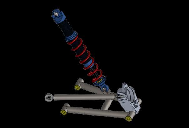
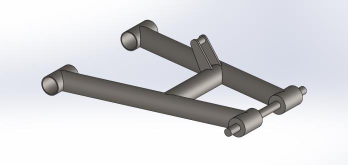
Figure 1 shows complete rear suspension assembly modeledonSOLIDWORKS2022
International Research Journal of Engineering and Technology (IRJET) e-ISSN:
Volume: 11 Issue: 04 | Apr 2024 www.irjet.net
1.2 Hardpoints
Hardpoints acts as pivot points for relative movement between suspension components and vehicle. These points are points on vehicle chassis where suspension connectstothevehicleframe.[4]
Table 1 shows considerations for the vehicle parameters to plot hardpoints in LOTUS SUSPENSION ANALYSIS v4.03.
Table -1: Vehicleconsiderations Dimension
Wheelbase(inmm)
TrackWidth(inmm)
HeightofCentreofgravity(H) (inmm)
KerbWeight(inkg)
Sprung/UnsprungMass (inkg)
Understandinghardpointshelpsindesigningvehiclesthat have improved performance as during acceleration, cornering and braking, the weight distribution within the vehicle dynamically shifts. The placement of hardpoints influences the weight transfer between the front and rear axles and also between the sides of the vehicle. Based on considerations for the accommodation of powertrain components and driver height, the wheelbase and track width of the ATV was set to achieve required turning radius. Further, based on the estimated weight, the hardpoints were designed keeping in mind the wheel traveloverbumpsanddroops.
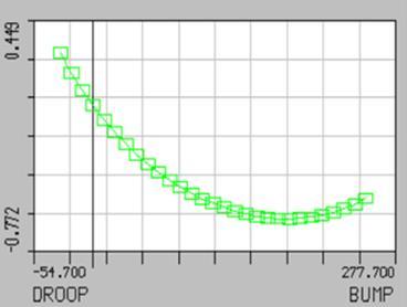
Due to the selection of H-Arm geometry, the toe variation wasalreadyeliminated.TheHardpointswereoptimizedto keep minimum variation in the camber angles to ensure proper grip is maintained throughout the wheel travel whilethevehiclegoesoverabumpordroop.Thetargetto keepthecambervariationoverwheeltravelwassettobe between-1degreeto+1degreewhichwasachievedandis shown in Chart 1 taken from LOTUS SUSPENSION ANALYSISv4.03 [5,6]
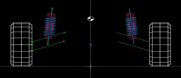
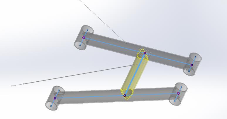
Figure 2 illustrates the visual representation of H-Arm suspension geometry modeled in LOTUS SUSPENSION ANALYSISv4.03.
1.3 Force Calculations
To perform static and dynamic analysis of the components, we have to take into account the various forcesresultingfromthevehicleconditionsovertherough terrain of the ATV. These conditions include braking, turning around a corner, navigating bumps and trenches. [7]
These forces arising from different conditions have been used as constraints in the FEA analysis software (ANSYS WORKBENCH 2022) to simulate adverse conditions that thevehiclewillhavetoendure.
The static analysis of the components performed with assumptions that will replicate the terrain conditions are asfollows:
a.NormalForce
b.BumpForce
c.CorneringForce
d.BrakingForce
a) Normal Force (Force due to self-weight):
The Normal force acting on the vehicle is the counterforce to the weight of the vehicle acting in the upwarddirection.
Fn=m*g
Fn =250kg*9.8m/s2 …(withweightof driver)
Fn=2450N
International Research Journal of Engineering and Technology (IRJET) e-ISSN: 2395-0056
Volume: 11 Issue: 04 | Apr 2024 www.irjet.net p-ISSN: 2395-0072
b) Bump Force:
ForcesthatactontheATVasitencountersbumpsand droops on the track are considered under bump force. When the ATV encounters a bump, the bump force is absorbed by the coil springs as it compresses and the same magnitude of force is given back during its expansion.
StiffnessofCoilSpring(k)=60.6N/mm
Maximumcompressionofspring(x)=80mm
Coilspringmakesanangleof85˚withthehorizontal axisofthewheel.
ForceappliedbyCoilSpring(f)= Stiffness(k)*Maximumcompression(x)
f=60.6*80
f=4848N
Verticalcomponentofaboveforce(fv)=f*sin(85˚)
fv=4829.55N
Figure3showsrepresentationofdistances(inmeters) L1 and L2 thathave been calculated using coordinates ofpointsobtainedfromLOTUSSUSPENSIONANALYSIS v4.03.
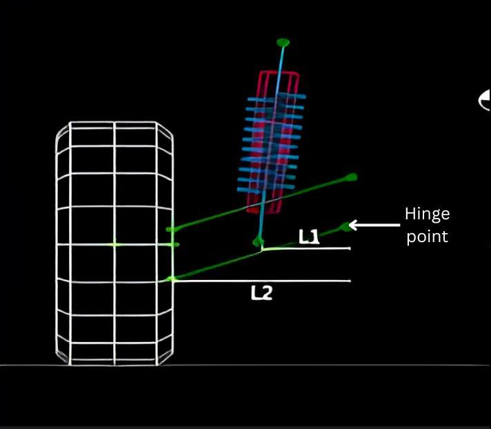
Fig -3:Respectivedistancesfromspring andouterpivot
Torqueappliedabouthinge=ForceappliedbyCoil Spring*L1
��=4829.55*0.146N-m
��=705.114N-m
BumpforceonUpright(Fb)=Torqueappliedabout hinge/L2
Fb =705.114/0.270N
Fb =2611.53N
Totakeintoaccountunknownforcesactedduring eventsofrolloverorimpactloading,bumpforceis consideredasthreetimestheweightofthevehicle.
c)
Cornering Force:
While turning around a corner, the ATV is acted on by centrifugal force and because of it the weight of the vehicleisshiftedtotheouterwheels.Thisisknownas cornering force. Cornering force determines the maximum lateral grip a vehicle can achieve before losing traction. Higher cornering forces generally indicate better traction, allowing the vehicle to maintaincontrolduringcorneringmaneuvers.
For the calculation of forces, we have only considered total mass on rear wheels (refer Table 1) to get accurateforcevalues.
TotalmassonRearWheels(mr)=167.5kg
Maxvelocityofvehicle(v)=50km/hr(Assumed) =13.9m/s
Fc=½*mr*v2
Fc=½*167.5*13.9
Fc=1164.125N
d) Braking Force:
During deceleration of the vehicle, the weight of the vehicle is shifted on the front axle. Force acting due to thisweighttransferisknownasbrakingforce. Braking force affects the distribution of weight and load transfer between the tyres during deceleration. Due to the weight transfer to the front axle, the grip in the front tyres increases and reduces the traction on the rear tyres. It may cause potential instability if the braking force exceeds the available traction on the tyres.
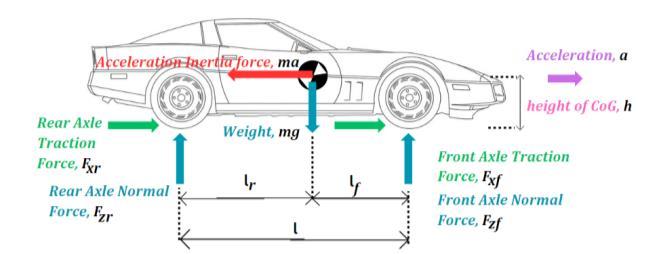
Fig -4:VehicleunderBraking
TotalmassonRearWheels(mr)=167.5kg
Brakingdistance(s)=7m
Lr =525mm
International Research Journal of Engineering and Technology (IRJET) e-ISSN: 2395-0056
Volume: 11 Issue: 04 | Apr 2024 www.irjet.net p-ISSN: 2395-0072
Lf =800mm
HeightofCentreofgravity(H)=610mm
Wheelbase(L)=1325mm
Maximumvelocityofvehicle(u)=50km/h=13.9m/s
v2 =u2 +2as
0=(13.9)2 +2*a*7
a=13.8m/s2 (deceleration)
Loadtransferontherearwheels,
Fbr=Wr+mr*a*(H/L)
Fbr=1225+167.5*13.8*(610/1325)
Fbr=2289.16N
Forces obtained from the previously discussed calculationsareusedinStaticandMultibodyAnalysis.
During Static and Multibody Analysis, we consider entire weightofvehicleononewheel.Thisisbecauseoftherare case where the vehicle may be airborne over very tall bumps that can result in the ATV landing on a single wheel. This results in the full weight of the ATV being placed on the suspension assembly of the corresponding wheel.
1.4 Design of H-Arms
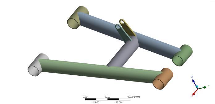
Hardpoints have been established using LOTUS SUSPENSIONANALYSISv4.03software.CAD modelingfor all suspension components was done on SOLIDWORKS 2022.DesignoftheH-Armswasdonearoundthesesetsof points which are fixed according to the geometry of the vehicle. These hardpoints influence the dynamics of the vehicle which allow for good traction, cornering and overall vehicle performance. Figure 5 shows plotting of hardpointsinSOLIDWORKS2022.

Fig -5: HardpointsplottedinSOLIDWORKS2022
Further,necessarylinesweresketchedandgeometry was createdaroundthem.Geometrywasthenextrudedaround the sketch using the Weldments feature in SOLIDWORKS 2022 as shown in Figure 6, thus giving us the required CADmodel.
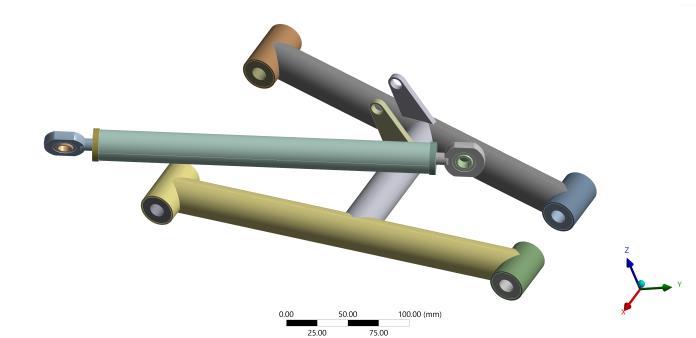
The H-Arm has been designed using hollow tubes of AISI 4130. Circular members of AISI 4130 were selected as theyhaveexcellentbendingstrengthandstiffness. Figures 7 and 8 have been taken from ANSYS WORKBENCH2022
The mountings of H-Arms were press fitted with polyurethane bushings to dampen vibrations. Mild steel inserts have been used to fit rod ends to the lateral link which provide articulation and structural integrity to sustain the stresses and loads of the tough terrain. Final constructionofthesuspensionarmisasfollows-
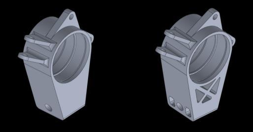
1.5 Rear Wheel Hub Design
DesignoftheWheelHubwasdonekeepinginmindallthe forcespreviouslydiscussedaboveintheforcecalculations and also depending on the dimensions of the assembly components, i.e. wheel rim, bearing, driveshaft and disc
International Research Journal of Engineering and Technology (IRJET) e-ISSN: 2395-0056
Volume: 11 Issue: 04 | Apr 2024 www.irjet.net p-ISSN: 2395-0072
brake rotor. Table 2 shows design parameters of the WheelHub.
Thisdesignhasbeenselectedasitcompletestheessential purpose of the component with minimum material being requiredforfabricationwithouthavingtocompromiseon its structural integrity. The material used for manufacturingof the Wheel Hub wasAl-7075-T6because ofitshighstrengthtoweightratio.
Table -2: WheelHubDesignParameters
PitchCircleDiameter(PCD) ofthewheelrim
PCDofthediscbrakerotor
DriveShaftOuterDiameter
BearingInnerDiameter
9 shows
144mm
75mm
24mm
35mm
1.6 Upright design
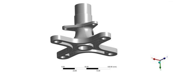
The Upright is a component that connects the Wheel Hub to the suspension arms. It is designed around hardpoints of the outer end of the suspension arms. To increase the costeffectivenessoftheresearch,Al6061-T6wasselected fortheUprightasitisnota hugecompromiseinstrength andotherimportantparameters.Bymeansofanalysis,the Upright wasoptimizedfrom itsfirst iteration asshown in Figure10
2. ANALYSIS
Our primary focus was to ensure minimum weight and maximum performance capability of the vehicle. Finite Element Analysis (FEA) is a computer-aided engineering tool that analyzes how a component design reacts under
real-worldconditions.Ithasbeenusedinourresearchfor conductingstructural analysis.ANSYSWORKBENCH2022 was used for all analyses in our research. It allowed us to generate analytical mathematical models and perform complex calculations to check the stresses and deformation developed in the CAD model of the component
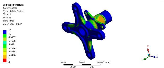
2.1 Rear Wheel Hub
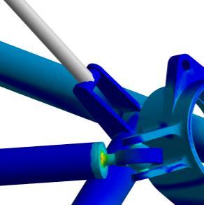
AnalysisoftheWheelHubgivesusvitalinformationabout its behavior when subjected to loading. It helps in weight reduction and thereby boosting the overall vehicle performance. After the analysis of the Wheel Hub, it was found that even after considering the weight of the whole ATV on a single wheel the minimum Factor of Safety (Factor of Safety is the ratio of the metal’s load bearing capacity to the actual load it experiences) was 1.9311 as shownbythelegendinFigure11.AsthevalueofFactorof Safety(F.O.S)isabove1,thecomponentwillwithstandthe loadssubjectedtoit.[8]
2.2 Rear Upright
Analysis of Upright gives us critical information which helps in optimization of the component. The Upright was subjectedtoalltheabovecalculatedforcesandresultedin FactorofSafety(F.O.S)of3.193asshownbyFigure12
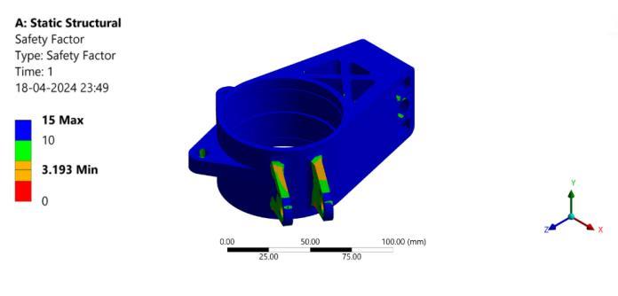
Fig -12: F.O.SofUpright
This indicates that the Upright will not undergo failure whensubjectedtoalltheaboveconsideredforces.
International Research Journal of Engineering and Technology (IRJET) e-ISSN: 2395-0056
Volume: 11 Issue: 04 | Apr 2024 www.irjet.net p-ISSN: 2395-0072
2.3 H-Arm Static analysis
H-Arms are responsible for making the connection of the unsprungmasstothestructuralmodulethatisassembled tothetubularchassisofthevehicle,therefore,theyarethe critical parts of the entire assembly since they are responsible for modifying and transmitting the forces actingonthesuspensionsystem.[9]DesignofH-Armshas been performed by knowing the behavior of the suspensioncomponentswiththeforcecalculationinorder tocheck whetherthegeometry oftheparts iscorrectand whether or not they are capable of withstanding the adverse conditions of difficult and bumpy terrain. The main design criteria for H-Arms of a suspension system are to maintain integrity without undergoing permanent deformation.
Following figures show the Static Analysis results of HArmobtainedinANSYSWORKBENCH2022-
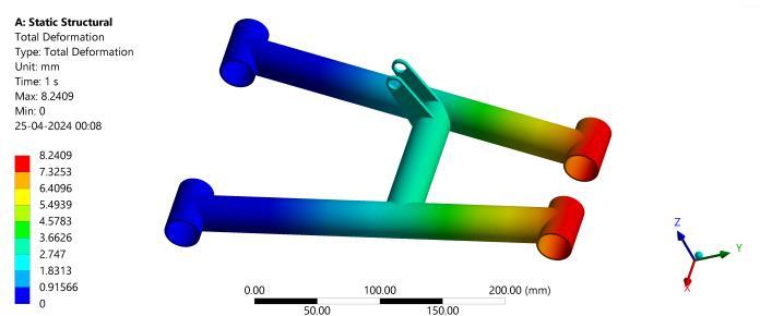
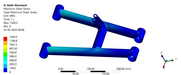
Upon performing necessary analysis on ANSYS WORKBENCH2022,weconcludethatthesuspensionarms oftherearsuspensionsystemcansustainthebump,brake and cornering resultant of force components with an acceptablemarginforFactorofSafety.
2.4 H-Arm Multibody Analysis:
AsimulationofMultibodyAnalysishasbeenperformed in ANSYS WORKBENCH 2022 to validate the results that we gotfromFiniteElement Analysisbyusingforcesobtained through static calculations and to simulate the entire assembly with time stepping to provide varying loading conditions. For Multibody Analysis, CAD model of the
components in the suspension assembly have been simplifiedtoreducethesolvingtimeoftheanalysis.
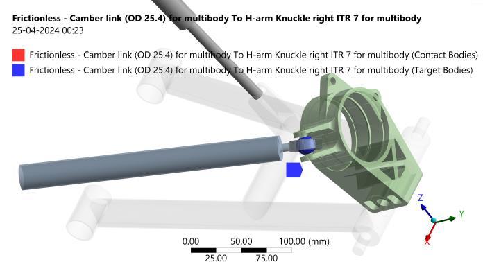
For this purpose, custom CAD model of the components have been created in SOLIDWORKS 2022. [10] Minimum contacts were necessary to improve the efficiency of the mechanicalsolverwithinAnsysWORKBENCH2022
Forthis,asinglelaterallink,insertandrodendentitywas createdtoeliminatethosecontactsasshowninFigure15 Similarly,aboltwasintegratedtotheH-Armthatconnects itwiththeUprightasshowninFigure16.

The number of contacts were reduced from 18 down to 2 contacts as shown in Figures 17 and 18. This greatly reduced the solving time and complexity without compromising the quality of analysis. Frictionless contact wasassignedtotherespectivecontactandtargetbodiesto simulatesmoothmotionduringwheeltravel.
International Research Journal of Engineering and Technology (IRJET) e-ISSN: 2395-0056
Volume: 11 Issue: 04 | Apr 2024 www.irjet.net p-ISSN: 2395-0072

Forshockabsorber,acustomspringdampermodelasper our specifications has been used which comes as a preinstalled package in the software (ANSYS WORKBENCH 2022) to make the simulation more accurate which is showninFigure18.
Meshing enhancement has been performed to improve overall mesh quality which then gives us more accurate results.Thiswasdonebyapplyingcomplexmeshmethods to adjust the proximity and curvature parameters that successfullycapturedthecomplexgeometryofthesystem.
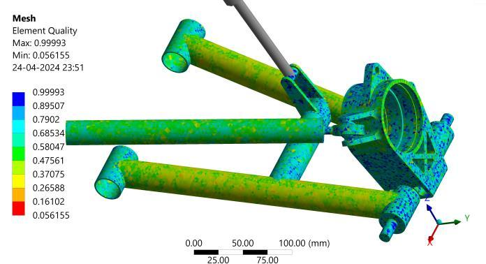
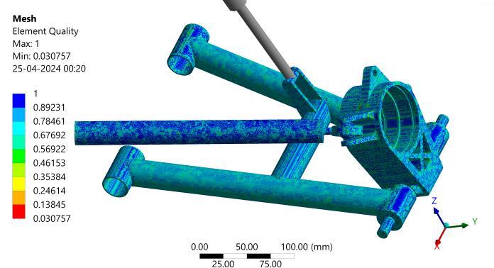
Necessary constraints such as fixed support, remote displacementtosimulatetherotationalfreedomofH-Arm about chassis mounting pivot and forces have been appliedtothemodel.
As explained at the end of force calculations, we have takenthefullweightoftheATVonasinglewheel.Table3 shows the force constraints of Multibody Analysis taken fromthepreviouslydiscussedforcecalculations
Table -3: ForceconstraintsofMultibodyAnalysis
xcomponent Brake 3678.8N
ycomponent Cornering 2943N
zcomponent Bump 7357.5N

Shear stress does not exceed the value of 450 MPa in the entire geometry except for the rod end connected to the Upright. This particular region highlighted by red color indicatesstressconcentrationasaresultofsharpedges in thegeometry.
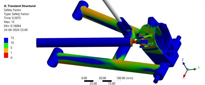
AnaverageF.O.Sof2.4wasachievedintheoverallH-Arm suspensionsystem.MinimumF.O.Sisachievedatthesame connection point between rod end and insert, thus indicating need for more resilient rod end. Rod end selection was done considering this extreme load at the connectionbetweenitselfandinsert.
Connectionpointsbetween tubes of theH-Armare joined using Tungsten Inert Gas (TIG) Welding, thus reinforcing
International Research Journal of Engineering and Technology (IRJET) e-ISSN: 2395-0056
Volume: 11 Issue: 04 | Apr 2024 www.irjet.net p-ISSN: 2395-0072
the component’s connection strength between those tubes.
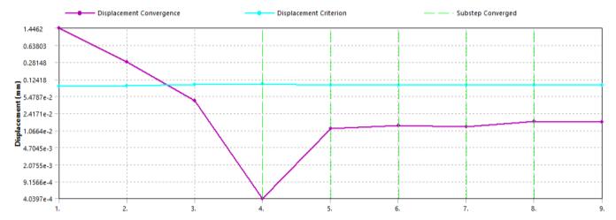
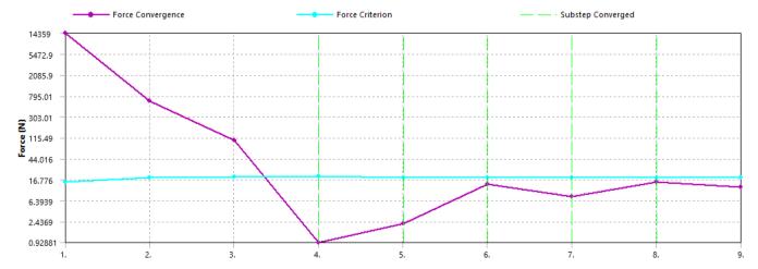
-3:Forceconvergencesolution
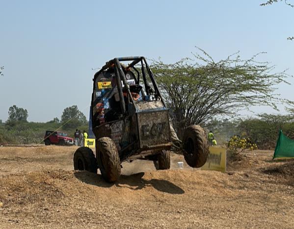
3. Testing and Validation:
Vehicle testing was carried out at a motorsport academy to evaluate the safety and reliability of the suspension system and check its overall performance and capability onamulti-facetedcoursewithchallengingterrain.
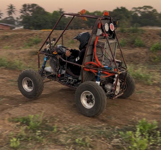
It was found that the suspension system was able to bear the loads of the tough terrain without affecting the structural integrity of the vehicle components. Upon rollover,followingpointswereobserved-
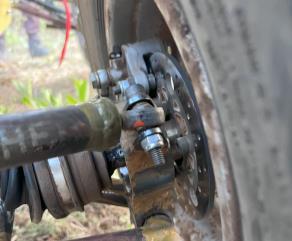
H-Arm: H-Arm experienced bending and twisting about chassis side mounting pivot after rigorous testingonvariousobstacle courses.Thenatureof bend of the fabricated component closely resembled the bend model demonstrated in analysisasshowninFigure24andPhotograph2
Rodend:Bendingwasinducedintherodenddue to extreme force and torsion, which resulted in
rod end failure as predicted by the analysis as showninFigure25andPhotograph3.
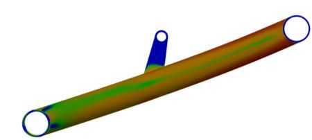

-25: Virtualrepresentationofstressconcentrationfor Rodend(Thisisazoomed-inpartofFigure21)
International Research Journal of Engineering and
Volume: 11 Issue: 04 | Apr 2024 www.irjet.net
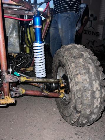
Table -4: Stressresultsofbothanalyses Component Stress (σ) (in MPa)
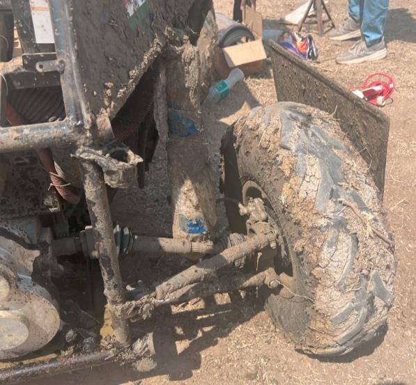
Table -5: F.O.Sresultsofbothanalyses
The results obtained from static analysis of both components has provided us with a good sense of understanding about the structural integrity of each componentandhowmuchloadcanbesustainedbythem.
Dynamic testing of the suspension system was conducted rigorously on an obstacle course, where the vehicle traversed various terrain challenges to evaluate its performanceanddurabilityunderreal-worldconditions.
To further test the vehicle’s limits and durability, we decided to enter the ATV in the 4-hour long Endurance race. The vehicle completed the Endurance Race without anymajordamageasshownbyouranalyses.
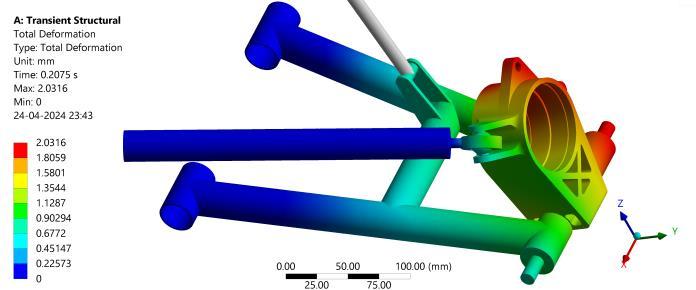
Multibody Analysis has been created with a transient simulation model using which we were able to simulate actual working conditions of the suspension and provide varyingloadsoverparticulartimeperiods.Thishashelped us understand the suspension behavior to a far greater extentbeyondthescopeofjuststaticanalysis.
Thus,boththesuspensionH-ArmsandUprightareableto withstand these extreme scenario force constraints, allowing us to design and manufacture robust rear suspensionsystemsthatcantackleanychallengingterrain withease.
4. CONCLUSION:
Design and structural analysis of the suspension system was done for weight reduction without compromising its loadbearingcapability.
International Research Journal of Engineering and Technology (IRJET) e-ISSN: 2395-0056
Volume: 11 Issue: 04 | Apr 2024 www.irjet.net p-ISSN: 2395-0072
The designs were meticulously reviewed and perfected over time, empirical methodology was used to optimize it even further. Improving mesh parameters and tweaking the analytical models gave us more insightful knowledge aboutthecomponents.
StaticanddynamictestswereperformedontheH-Armsto testitspracticalityandfunctionality.
Subsequently, Multibody Analysis was done on the assembled rear suspension to see whether the components work together harmoniously and withstand theforcesactingonthem.
After such intricate and continuous evaluation, we would liketoconcludethattheH-ArmSuspensionSystemwitha SingleUpperLateralLinkisaviableoptionwhilechoosing aRearSuspensionSystemforanAllTerrainVehicle
5. REFERENCES
[1] Dishant, Er. Parminder Singh, Er. Mohit Sharma (2017). Suspension Systems: A Review. International Research Journal of Engineering and Technology (IRJET).
[2] Milliken, William F. & Milliken, Douglas L. (1995). Race Car Vehicle Dynamics. Warrendale, PA, U.S.A.: SAEInternational.
[3] Blundell, M. & Harty D. (2004) The Multibody System ApproachtoVehicleDynamics.Elsevier.
[4] Gurpreet Singh, Abhinav Kumar, Saurabh Menwal (2023). Suspension and chassis design, and steering calculations for SAE BAJA All-Terrain Vehicle. International Research Journal of Engineering and Technology(IRJET).
[5] Khan Noor Mohammad, Vatsal Singh, Nihar Ranjan Das, Prajwal Nayak, B.R. Patil (2018). Dynamic Analysis of the Front and Rear Suspension System of an All Terrain Vehicle. International Research Journal ofEngineeringandTechnology(IRJET).
[6] Sumit Sharma (2020). Design Review of Suspension Assembly of a BAJA ATV. International Research JournalofEngineeringandTechnology(IRJET).
[7] Kritika Singh, Kanishka Gabe (2020). Calculation of Dynamic Forces and Analysis of Front Upright for ATV. International Research Journal of Engineering andTechnology(IRJET).
[8] Bhandari V. B. (2010). Design of Machine Elements. TataMcGraw-HillEducation.
[9] Parag Borse, Vaishnav Mayekar, Nilesh Jain. Design and Development of H-Frame with Lateral Link Suspension for an All Terrain Vehicle. International Research Journal of Engineering and Technology (IRJET).
[10] ShlokK.Laddha,HritikS.Jain(2021).Design,Analysis and Optimization of Trailing Arm with Two Link Suspension System. International Journal of Research andAnalyticalReviews(IJRAR).
6. BIOGRAPHIES


Rajvardhan Sawant
A production engineer from VJTI Mumbai. Prowess in Suspension ArmsandCAD/CAE.

Atharva Bagwe
A production engineer from VJTI Mumbai. Prowess in suspension systemsandCAD/CAE

Rahul Barbude
A mechanical engineer from VJTI Mumbai. Prowess in Suspension hardpointsandCAD.

Vishwesh Chauhan
A production engineer from VJTI Mumbai. Prowess in Power TransmissionandCAD/CAE.

Dr. Padmashri Patil
Assistant Professor, Dept of Physics, VJTI Mumbai. Ph. D. in PhysicsfromIISERPune.